
Magnetite dry grinding and dry separation method and device

A dry separation method and magnetite technology, applied in chemical instruments and methods, magnetic separation, solid separation, etc., can solve the problem of large particle size of the crusher output affecting the efficiency of magnetic separation, high power consumption and steel consumption of tube mills, and tailings Solve the problems of high cost, achieve the effect of ensuring the recovery rate of all iron, solving the large water consumption, and improving the quality of iron ore

Active Publication Date: 2015-08-05
成都建筑材料工业设计研究院有限公司
View PDF7 Cites 18 Cited by
  • Summary
  • Abstract
  • Description
  • Claims
  • Application Information

AI Technical Summary

Problems solved by technology

The tube mill has high power consumption and steel consumption, and the general fine grinding adopts wet ball mill, which consumes a lot of water, the cost of tailings treatment is high, and it has great environmental pollution
In recent years, some technologies have also introduced high-pressure roller mills into the iron ore grinding system, but only replaced part of the fine crushing and coarse grinding, and solved the problem that the large particle size of the crusher affects the efficiency of magnetic separation, but the high-pressure roller The material after grinding by the mill needs to be finely ground by the tube mill, which has not fully solved the problems of high energy consumption and large water consumption of the tube mill

Method used


Image

  • Magnetite dry grinding and dry separation method and device

Examples


Embodiment Construction

[0024] The following non-limiting examples illustrate the invention.

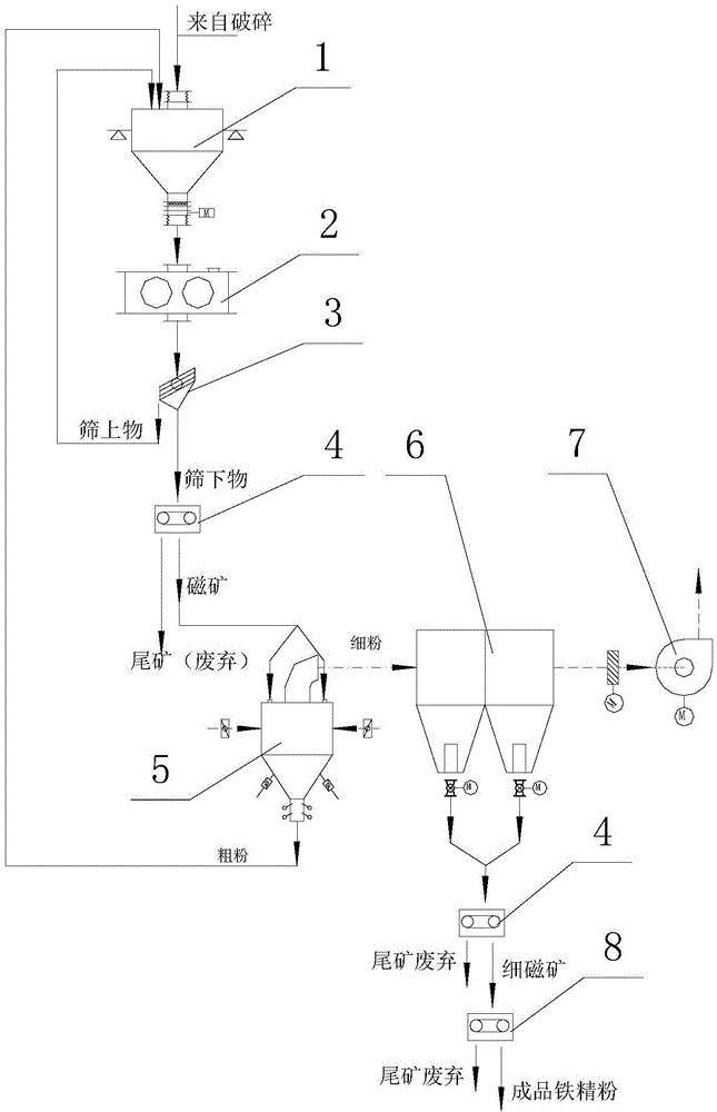
[0025] refer to figure 1 As shown, the ore <80mm after crushing and magnetic separation is directly sent to the high-pressure roller buffer bin 1 through the belt, or, after being finely crushed to <30mm, it is sent to the high-pressure roller buffer bin 1, and the ore is first mixed with the coarse-grained return material in the buffer bin , after being squeezed by the high-pressure roller 2, it is sent to the linear vibrating screen 3 for screening by the belt. The sieved material (<3mm) of the linear vibrating screen 3 enters the dry magnetic separator 4 for separation, the waste rock is sent to the waste rock storage yard through the belt, and the coarse concentrate is sent to the wind power separator 5 for classification through the belt conveyor and the hoist. After grading, the coarse powder (<3mm) is sent back to the high-pressure roller buffer chamber 1 through the belt to continue extrusion, and ...


PUM


Abstract

The invention discloses a magnetite dry grinding and dry separation method and a magnetite dry grinding and dry separation device, and belongs to the technical field of iron ore selection and grinding. The method comprises the steps of mixing secondarily crushed ore with particle size less than 80mm and coarse-grain return scrap to obtain a mixture I, extruding the mixture I by virtue of a high pressure roller, and mechanically screening the mixture I, wherein the screening granularity is 3mm; returning an oversize product adopted as the coarse-grain return scrap to the high pressure roller to be continuously extruded, separating screen underflow in a dry-type magnetic separator, grading rough concentrate separated by the dry-type magnetic separator by virtue of a wind power powder separation machine, returning coarse powder graded by the wind power powder separation machine and adopted as coarse-grain return scrap to the high pressure roller to be continuously extruded, collecting fine powder meeting the fineness requirement of iron fine powder after the grading of the wind power powder separation machine, separating the fine powder by virtue of the dry-type magnetic separator, and finally carrying out the wet-type magnetic separation for fine magnetic minerals meeting the fineness requirement of the iron fine powder after the separation of the dry-type magnetic separator. By adopting the magnetite dry grinding and dry separation method, the crushing grinding and the magnetic separation of the ore are reasonably matched, so that the system energy consumption is reduced, consumption of steel and water is reduced, and the environmental pollution is alleviated.

Description

technical field [0001] The invention belongs to the technical field of iron ore beneficiation and grinding. Background technique [0002] In the magnetite beneficiation industry, the preparation of iron concentrate powder needs to reach a certain grade and fineness. In the process of gradually reducing the particle size of iron ore raw ore and gradually improving the grade, since the magnetic separation efficiency has an obvious relationship with the particle size of iron ore , and to achieve a certain particle size requires corresponding work and energy consumption. Considering the maximization of economic benefits, it is necessary to reasonably select the ore particle size corresponding to each level of magnetic separation. The traditional crushing and grinding is mainly completed by crusher and tube mill. Because the crusher is limited by equipment performance and power consumption, it can only be carried out to the fine crushing stage (generally crushing to <12mm), an...

Claims


Application Information

Patent Timeline
IPC IPC(8): B02C21/00
CPCB02C21/00B02C23/00B02C23/14B03C1/00
Inventor 李鹏斌刘建郭华琛张莉
Owner 成都建筑材料工业设计研究院有限公司
Learn More