Fault diagnosis method and device for rolling bearing of running gear of locomotive
A fault diagnosis device and technology for rolling bearings, which are applied in the fields of mechanical bearing testing, computer parts, character and pattern recognition, etc., can solve the problems of low diagnostic accuracy and long time-consuming to establish a diagnostic model, and achieve high classification accuracy and training time. The effect of short, improved speed and accuracy
- Summary
- Abstract
- Description
- Claims
- Application Information
AI Technical Summary
Problems solved by technology
Method used
Image
Examples
Embodiment 1
[0075] Such as figure 1 Shown is a flow chart of a method for diagnosing a rolling bearing fault in a running part of a locomotive according to an embodiment of the present invention. The method includes:
[0076] Step S101: Collect the vibration acceleration data of the rolling bearings of the running part of the locomotive under different fault types, and group the data according to the fault types. The total number of groups is A. The four different fault types include: normal signal, inner ring fault, outer ring fault Faults and rolling element failures;
[0077] The four working conditions of normal signal, inner ring fault, outer ring fault and rolling element fault represent the fault types of locomotive rolling bearings, which can be represented by 1, 2, 3, and 4 in the fault diagnosis model established by the subsequent method.
[0078] Step S102: Obtain the frequency domain signal of the vibration acceleration data according to the grouped vibration acceleration dat...
Embodiment 2
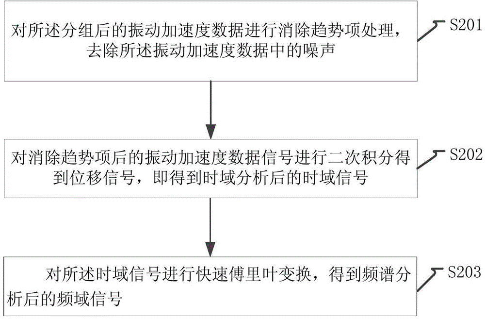
[0089] Such as figure 2 Shown is a flow chart of another method for diagnosing a rolling bearing fault in the running part of a locomotive according to an embodiment of the present invention, which is a specific description of step S102, including:
[0090] Step S201: Perform trend elimination processing on the grouped vibration acceleration data to remove noise in the vibration acceleration data;
[0091] Step S202: Perform secondary integration on the vibration acceleration data signal after the trend item is eliminated to obtain the displacement signal, that is, obtain the time domain signal after time domain analysis;
[0092] Step S203: performing fast Fourier transform on the time-domain signal to obtain a frequency-domain signal after spectrum analysis.
[0093] This embodiment is a refinement of step S102, and has all the technical effects of the first embodiment, and will not be repeated here.
Embodiment 3
[0095] Such as image 3 Shown is a flow chart of another method for diagnosing rolling bearing faults in the running part of a locomotive according to an embodiment of the present invention, which is a specific description of step S103, including:
[0096] Step S301: Perform three-layer wavelet packet decomposition on the denoised group A frequency domain signals, and obtain 8 frequency domain components f for each group of signals 1 / 8 , f 2 / 8 , f 3 / 8 , f 4 / 8 , f 5 / 8 , f 6 / 8 , f 7 / 8 , the signal of f;
[0097] Three-layer wavelet packet decomposition, that is, one-dimensional third-order fast wavelet transform, uses multiple iterations of wavelet transform to analyze the input signal, so after three wavelet transforms, as Figure 4 shown.
[0098] Step S302: Calculate the energy E of each frequency domain component of the frequency domain signal 1 / 8 ,E 2 / 8 ,E 3 / 8 ,E 4 / 8 ,E 5 / 8 ,E 6 / 8 ,E 7 / 8 ,E, construct the energy eigenvector of A*8 Xi =...
PUM
 Abstract
Description
Claims
Application Information
 - R&D
- Intellectual Property
- Life Sciences
- Materials
- Tech Scout
- Unparalleled Data Quality
- Higher Quality Content
- 60% Fewer Hallucinations
Browse by: Latest US Patents, China's latest patents, Technical Efficacy Thesaurus, Application Domain, Technology Topic, Popular Technical Reports.
© 2025 PatSnap. All rights reserved.Legal|Privacy policy|Modern Slavery Act Transparency Statement|Sitemap|About US| Contact US: help@patsnap.com


