RRAM voltage generating system

A voltage and reference voltage technology, applied in the field of RRAM voltage generation system, can solve the problems of low power efficiency, increased chip cost, and no support for simultaneous operation of multi-byte Bytes memory cells, so as to achieve the effect of improving speed and reducing chip cost.

Active Publication Date: 2015-07-15
XI AN UNIIC SEMICON CO LTD
View PDF9 Cites 4 Cited by
  • Summary
  • Abstract
  • Description
  • Claims
  • Application Information

AI Technical Summary

Problems solved by technology

[0011] Although the above-mentioned existing scheme can provide all required voltages for RRAM, there are still the following disadvantages: 1) This scheme does not support simultaneous operation of multi-byte Bytes storage units; it is mentioned in the original text that the charge pump adopts a Dickson charge pump, and its load The maximum is 1mA; it can be speculated that this solution is only used to support the simultaneous SET/RESET operation of memory units less than 1 byte (8bits); if it is necessary to support multiple bytes (eg 16Bytes=128bits) memory units simultaneously SET/RESET operation, that is, the load current of the charge pump will be very large (>16mA); 2) Using a 3-stage Dickson charge pump, the voltage loss is large, the load driving ability is low, and the power efficiency is low; to...

Method used


Image

  • RRAM voltage generating system
  • RRAM voltage generating system
  • RRAM voltage generating system

Examples


Embodiment Construction

[0038] The present invention will be further described in detail below in conjunction with specific embodiments, which are explanations of the present invention rather than limitations.

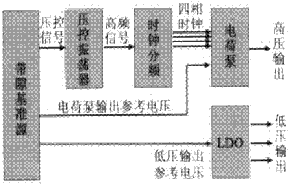
[0039] The RRAM voltage generating system of the present invention, such as Figure 4 As shown, it is the schematic diagram of the overall system of RRAM and the schematic diagram of the voltage generation system of the present invention, wherein the voltage generation system 1 circled by the thick dotted line provides the required voltage for the row and column decoder 2 and the memory cell array 3 .

[0040] Among them, the voltage generation system 1 is composed of five parts: a voltage and current reference source 11 , a charge pump 12 , a square wave oscillator 13 , a linear voltage regulator 14 and a power-on control circuit 15 . Voltage and current reference source 11 provides reference voltage and reference current after temperature compensation and trimming for other circuits (square...


PUM


Abstract

The invention discloses an RRAM voltage generating system. The RRAM voltage generating system comprises an electric charge pump, a square-wave oscillator, a linear voltage stabilizer, an electrifying control circuit and a voltage and current reference source, wherein the electric charge pump is used for rising the voltage of an external power supply and providing power for other sub circuits; the square-wave oscillator is used for providing a clock signal; an output end of the square-wave oscillator is connected with a clock signal input end of the electric charge pump; the linear voltage stabilizer is used for providing driving voltage for the operation of a storage unit, and an output end of the linear voltage stabilizer is sequentially connected with a row and column decoder and a storage unit array; the linear voltage stabilizer is synchronously connected with an external power supply VCC and an electric charge pump output power supply VPP for supplying power; the electrifying control circuit is used for providing an electrifying reset signal for the system and meanwhile controlling the ordered start of the electric charge pump, the square-wave oscillator and the linear voltage stabilizer; the voltage and current reference source is used for providing reference voltage and reference current for the electric charge pump, the square-wave oscillator, the linear voltage stabilizer and the electrifying control circuit. An external power supply and the electric charge pump of a double-branch structure with good technological compatibility are adopted for supplying power respectively for the linear voltage stabilizer, and support multiple bites.

Description

technical field [0001] The invention relates to the field of memory, in particular to an RRAM voltage generation system. Background technique [0002] Resistive random access memory (RRAM) is a new type of non-volatile information storage technology, which has the characteristics of simple structure, compatible with standard CMOS technology, low operating voltage, low power consumption and high-speed reading and writing. Its storage information unit is realized by a variable resistor exhibiting bipolar memory characteristics of a high resistance state (for example: 100Kohm) and a low resistance state (for example: 10Kohm). [0003] In order to convert the variable resistor between the low-resistance state and the high-resistance state, it is necessary to configure the variable resistor under different voltage or current working conditions. [0004] figure 1 Shown is a group of typical 1T1R (1 transistor and 1 variable resistor) memory cell voltage configuration diagrams, w...

Claims


Application Information

Patent Timeline
IPC IPC(8): G11C13/00
CPCG11C13/00
Inventor 谢永宜
Owner XI AN UNIIC SEMICON CO LTD
Why Eureka
Try Eureka