Dielectric barrier discharge-type electrode structure for generating plasma having conductive body protrusion on electrodes

A technology of dielectric barrier discharge and electrode structure, which is applied in the installation/support/configuration/insulation of plasma, corona discharge devices, electrode assemblies, etc. problem, to achieve excellent plasma efficiency, excellent power consumption, and low air back pressure

Active Publication Date: 2015-07-01
SP TECHNOLOGY CO LTD
View PDF19 Cites 20 Cited by
  • Summary
  • Abstract
  • Description
  • Claims
  • Application Information

AI Technical Summary

Problems solved by technology

However, according to these methods, a loss of pressure occurs due to the dielectric filled in the reactor, and the reactor is easily clogged when particulate matter is present in the exhaust gas.
Moreover, in order to treat a large amount of exhaust gas, it is necessary to bundle a plurality of tubular reactors into a bundle or a pile, so the size of the treatment system will be greatly enlarged.

Method used


Image

  • Dielectric barrier discharge-type electrode structure for generating plasma having conductive body protrusion on electrodes
  • Dielectric barrier discharge-type electrode structure for generating plasma having conductive body protrusion on electrodes
  • Dielectric barrier discharge-type electrode structure for generating plasma having conductive body protrusion on electrodes

Examples


Embodiment 1

[0145] To evaluate the performance of the plasma electrode structure, an air cleaner module consisting of a fluid inlet, a plasma electrode, and a fluid outlet was used. The energized electrode is made of stainless steel 403 and has a circular plate shape with a diameter of 50mm and a thickness of 1mm. Using a stamping method, five are distributed on the outer profile of the diameter of the plate at a consistent angle, with a height of 50μm. The electrode protrusions are formed again in the same way at the central part of the radius to make 5 protrusions. In addition, 48 circular through-holes with a diameter of 3.6mm are evenly distributed on the board. Its open area is 25% of the total area. After that, aluminum oxide and barium titanate powder with a particle size of 1-2um are used as dielectric components, and polyvinylidene fluoride (PVDF, Polyvinylidene fluoride) as a polymer is used as a binder, through a typical spraying (spray) process , form a dielectric layer with...

Embodiment 2

[0149] The electrical energy applied to the electrodes is measured, i.e., the number of anions generated as the pulse width increases, and at Figure 13 is shown in . Such as Figure 13 As shown, it can be known that the number of anions generated increases at an extremely fast rate with the increase of the pulse width, and when the pulse width is close to 100 μs, the number of anions per cubic centimeter is close to 1 million.


PUM

PropertyMeasurementUnit
currentaaaaaaaaaa
diameteraaaaaaaaaa
diameteraaaaaaaaaa

Abstract

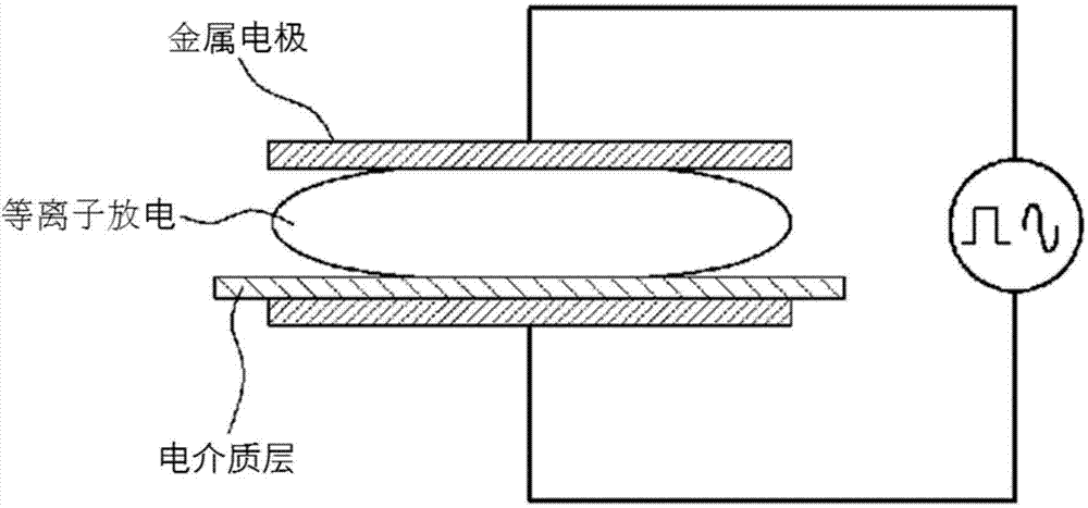
Provided is a dielectric barrier discharge-type electrode structure for generating plasma. The electrode structure, according to the present invention, comprises: an upper conductive body electrode and a lower conductive body electrode; at least one conductive body electrode protrusion portion, which is formed on at least one surface of the upper conductive body electrode and / or the lower conductive body electrode; a dielectric layer which is formed on at least one of the inner surfaces of the upper conductive body electrode and the lower conductive body electrode that face each other, so as to have a substantially uniform thickness; and a specific gap (d) which is formed between the upper and lower conductive body electrodes and the dielectric layer, or between dielectric layers, due to the protruding effect of the conductive body electrode protrusion portion when the upper conductive body electrode and the lower conductive body electrodes come into close contact, wherein the plasma is generated by applying a pulse power or an alternating power to the upper conductive body electrode and the lower conductive body electrode.

Description

technical field [0001] The present invention relates to the plasma electrode structure that is applied to air purification system etc. and similar system, relates to the dielectric barrier discharge (DBD, Dielectric Barrier Discharge) type plasma generation electrode structure in more detail, and described electrode knot is stored in gaseous fluid such as air Plasma is generated, and the electrons, ions, and ultraviolet rays generated at this time react with bacteria and odor molecules to decompose harmful gases and sterilize them, thereby purifying the air inside air conditioners, refrigerators, washing machines, and vehicles. Background technique [0002] As indoor air purification becomes increasingly important, various methods for simultaneously removing particles and gaseous substances present in the room have been developed. These air purification technologies include filtration, electrostatic precipitator, plasma, UV / photocatalyst, and hybrid methods. [0003] Among ...

Claims


Application Information

Patent Timeline
Patent Type & Authority Applications(China)
IPC IPC(8): H01T19/04H01T23/00
CPCH05H2001/2412A61L9/22H01J1/02A61L2/14H05H1/2406H05H2001/2437H01T23/00H01T19/04H01J1/88H05H1/2437B01D53/32H05H1/34
Inventor 孙熙植
Owner SP TECHNOLOGY CO LTD
Why Eureka
Try Eureka