
Plasma air disinfection and purification device

A plasma and air disinfection technology, used in disinfection, air conditioning systems, space heating and ventilation, etc., can solve the problems of difficulty in ensuring disinfection and purification effect, small amount of plasma, low sterilization speed and low energy consumption, and achieve strong disinfection effect. , High plasma concentration and long service life

Inactive Publication Date: 2015-07-01
LIANYUNGANG YOUYUAN MEDICAL EQUIP MFG
View PDF5 Cites 6 Cited by
  • Summary
  • Abstract
  • Description
  • Claims
  • Application Information

AI Technical Summary

Problems solved by technology

The use effect of ultraviolet lamps is inversely proportional to the time and radiation intensity. Generally, the lamp tube needs to be replaced when the service life does not exceed 1000 hours. The loss is relatively large, and ultraviolet radiation is harmful to human skin and eyes, so it cannot be used in the presence of people.
[0005] Compared with the traditional ozone air disinfection and ultraviolet air disinfection, the plasma air disinfection method has the characteristics of fast sterilization speed, no secondary pollution, low energy consumption, etc., can decompose organic pollutants such as formaldehyde and benzene, and can coexist in human and machine It can be used in a wide range of places, but the discharge positive and negative electrodes in the current plasma air disinfection machine on the market are in the form of a strip discharge, and the amount of plasma generated is very small, which cannot meet the requirements of the national qualification testing department. The plasma concentration is low, and it is difficult to ensure a good disinfection and purification effect under the condition of fast air circulation

Method used


Image

  • Plasma air disinfection and purification device
  • Plasma air disinfection and purification device
  • Plasma air disinfection and purification device

Examples


Embodiment Construction

[0017] The specific technical solutions of the present invention will be further described below with reference to the accompanying drawings, so that those skilled in the art can further understand the present invention, without limiting their rights.

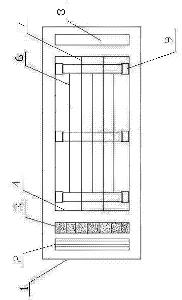
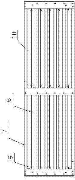
[0018] refer to figure 1 , figure 2 and image 3 , a plasma air disinfection and purification device, comprising a housing 1, one side of the housing 1 is provided with an air inlet, the other side is provided with an air outlet, the air inlet is provided with an air dust filter 2, and the air outlet is provided with Be provided with photocatalyst filter 8, be provided with plasma generation chamber 4 between photocatalyst filter 8 and air dust removal filter 2, be provided with plasma generation device in plasma generation chamber 4, described plasma generation device includes A plurality of electrode plates 7 arranged at intervals up and down, the electrode plates 7 are arranged horizontally along the direction from the ai...


PUM


Abstract

A plasma air disinfection and purification device comprises a shell in which a plasma generation cavity is formed, a plasma generating device is arranged in the plasma generation cavity and comprises a plurality of electrode plates which are arranged at intervals in an up-and-down mode and horizontally arranged from an air inlet to an air outlet, insulating supports are arranged at the air outlet ends and the air inlet ends of the electrode plates, at least one electrode band is arranged between every two adjacent electrode plates, the two ends of each electrode band are installed on the insulating supports, edge teeth extending to the two outer sides of each electrode band are arranged on the two lateral sides of the electrode band, when a power source is switched on, horn-shaped glow discharge is generated between each edge tooth of each electrode band and the upper electrode plates as well as between each edge tooth of each electrode band and the lower electrode plates, discharge areas coincide in a crossed mode, and high-density plasma is generated. According to the device, due to the arrangement of the electrode bands, the wire breakage problem of wire electrodes is solved, and service life is longer; the edge teeth are arranged, horn-shaped glow discharge is generated, and the disinfection effect is stronger.

Description

technical field [0001] The invention relates to an air disinfection and purification device, in particular to a plasma air disinfection and purification device. Background technique [0002] At present, the widely used air disinfection method adopts ozone disinfection or ultraviolet disinfection method, and the plasma air disinfection method is gradually used. [0003] The ozone disinfection method is to convert oxygen ions (0 2- ) ionized into reactive oxygen species (O 3 ), an oxygen generator or an oxygen tube is required, and the ozone must reach a certain concentration in order to play a role in sterilization. Ozone concentration in the air reaches 0.01-0.02mg / m 3 Odor can be smelled from time to time, and the ozone concentration in the air reaches 0.1mg / m 3 When it is used, it will irritate the eyes, nose, throat and respiratory tract of people, and has a toxic effect on the human body. It cannot be used when there are people. People can only enter the room aft...

Claims


Application Information

Patent Timeline
IPC IPC(8): F24F1/00F24F13/28F24F13/00A61L9/22
CPCF24F8/10F24F8/158F24F8/167F24F8/192F24F8/30
Inventor 张建斌陈长才肖雷
Owner LIANYUNGANG YOUYUAN MEDICAL EQUIP MFG
Learn More