Frequency reconfigurable waveguide slot antenna based on dual transverse pin diodes
A technology of PIN diode and waveguide slot antenna is applied in the field of frequency reconfigurable waveguide slot antenna to achieve the effect of reducing complexity and cost
- Summary
- Abstract
- Description
- Claims
- Application Information
AI Technical Summary
Problems solved by technology
Method used
Image
Examples
Embodiment 1
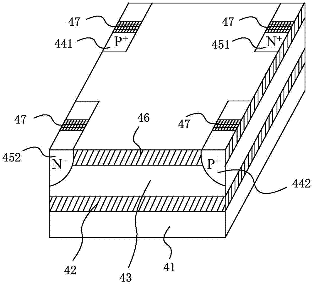
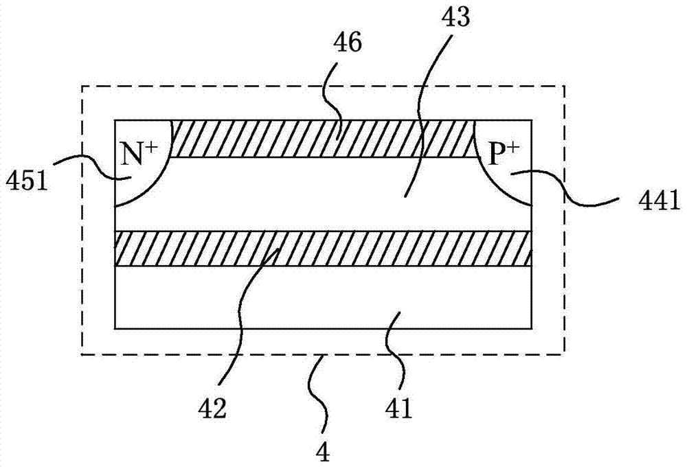
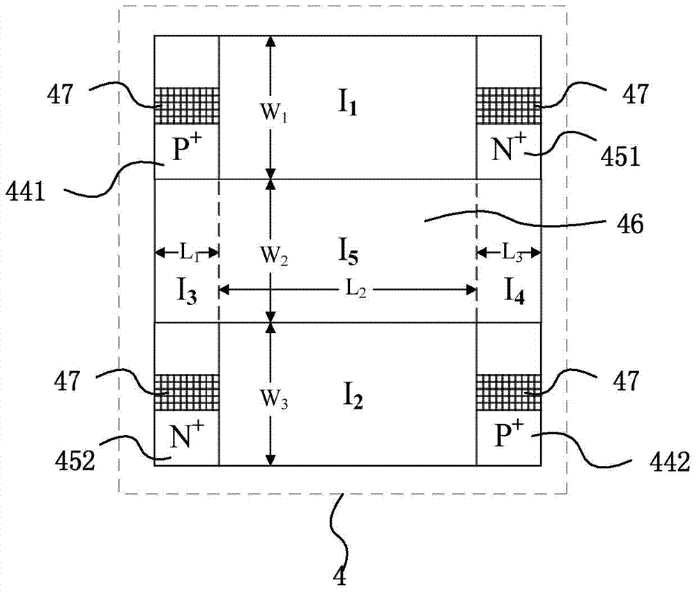
[0025] Such as Figure 7 As shown, this frequency reconfigurable waveguide slot antenna based on double transverse PIN diodes includes a servo circuit 1 , a programmable voltage source 2 , and a rectangular waveguide 3 . Cut n slots on the wide wall of the rectangular waveguide 3, and the range of n is 8-64 (see Figure 5 with Image 6 ), a dual lateral PIN diode 4 is respectively placed in each slit, wherein the top view of the dual lateral PIN diode 4 is as follows image 3 shown.
[0026] For the convenience of expression, it is assumed in this example that only 8 slots 301-308 are cut in the wide wall of the waveguide, as Figure 8 As shown, the slits of the wide wall of the waveguide are parallel to the long edges of the rectangular waveguide, and the longitudinal distance between the slits is λ / 2, where λ is the wavelength of the waveguide; a double transverse PIN diode 4 is respectively installed at the slits 301-308, and the double transverse The length and width of...
Embodiment 2
[0035] Such as Figure 7 As shown, this frequency reconfigurable waveguide slot antenna based on double transverse PIN diodes includes a servo circuit 1 , a programmable voltage source 2 , and a rectangular waveguide 3 . Cut n slots on the wide wall of the rectangular waveguide 3, and the range of n is 8-64 (see Figure 5 with Image 6 ), a dual lateral PIN diode 4 is respectively placed in each slit, wherein the top view of the dual lateral PIN diode 4 is as follows image 3 shown. For the convenience of expression, it is assumed in this example that only 8 slots 301-308 are cut in the wide wall of the waveguide, as Figure 8 shown. In this example, the connection mode of each part of the frequency reconfigurable waveguide slot antenna based on double transverse PIN diodes is exactly the same as that in Embodiment 1.
[0036] For the convenience of expression, it is assumed that the length and width of all the waveguide slots 301-308 are respectively equal, and the length...
Embodiment 3
[0040] The servo circuit 1 controls the programmable voltage source 2 by programming, so that the programmable voltage source 2 outputs multiple voltages that meet the programming requirements; the multiple voltages output by the programmable voltage source 3 are connected to the corresponding double horizontal PIN diodes 4 to control the dual Different parts of the lateral PIN diode 4 are turned on and off. By controlling the length, width and offset distance of the slots 301-308 of the rectangular waveguide 3 in this way, it can be expanded according to the above-mentioned ideas, and other different dual-based Frequency reconfigurable waveguide slot antenna with transverse PIN diode.
PUM
 Abstract
Description
Claims
Application Information
 - R&D Engineer
- R&D Manager
- IP Professional
- Industry Leading Data Capabilities
- Powerful AI technology
- Patent DNA Extraction
Browse by: Latest US Patents, China's latest patents, Technical Efficacy Thesaurus, Application Domain, Technology Topic, Popular Technical Reports.
© 2024 PatSnap. All rights reserved.Legal|Privacy policy|Modern Slavery Act Transparency Statement|Sitemap|About US| Contact US: help@patsnap.com


