
Combined giant column composed of irregular-section multi-cavity steel tube with built-in concrete-filled circular steel tube, and construction method thereof

A special-shaped cross-section, round steel pipe technology, applied in the direction of columns, pier columns, pillars, etc., can solve the problems of damage, stress concentration, etc., and achieve the effects of economical and effective, high bending bearing capacity, and overcoming brittleness

Active Publication Date: 2015-06-17
BEIJING UNIV OF TECH
View PDF11 Cites 15 Cited by
  • Summary
  • Abstract
  • Description
  • Claims
  • Application Information

AI Technical Summary

Problems solved by technology

[0004] The purpose of the present invention is to provide a multi-cavity composite giant column with special-shaped cross-section and multi-cavity concrete-filled steel pipe with simple construction and low cost, in order to solve the problem of local damage caused by the stress concentration of the multi-cavity steel-filled steel composite giant column with special-shaped cross-section, and at the same time alleviate the large volume Concrete Temperature Cracks Caused by Concrete Hydration Heat

Method used


Image

  • Combined giant column composed of irregular-section multi-cavity steel tube with built-in concrete-filled circular steel tube, and construction method thereof
  • Combined giant column composed of irregular-section multi-cavity steel tube with built-in concrete-filled circular steel tube, and construction method thereof
  • Combined giant column composed of irregular-section multi-cavity steel tube with built-in concrete-filled circular steel tube, and construction method thereof

Examples


Embodiment Construction

[0034] In order to better understand the present invention, the content of the present invention will be further explained below in conjunction with the accompanying drawings.

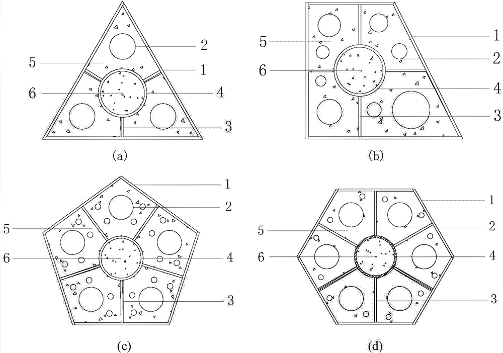
[0035] as attached figure 1 And attached Figure 7 , a multi-cavity steel pipe with special-shaped cross-section built-in circular steel pipe concrete composite giant column, including steel pipe 1, transverse diaphragm 2, longitudinal stiffener 3, and round steel pipe 4; The unit can be triangular, quadrilateral, pentagonal, or hexagonal in cross-section, with a built-in round steel pipe 4, internally welded with transverse diaphragms 2 and longitudinal stiffeners 3, pouring ordinary high-strength concrete 5 inside the steel pipe 1, and pouring inside the round steel pipe 4 High-performance high-strength concrete 6. attached figure 2 The original design section for Tianjin 117 super high-rise building, attached image 3 in the attached figure 2 Built-in round steel pipes at the corners on the b...


PUM

PropertyMeasurementUnit
thicknessaaaaaaaaaa

Abstract

The invention relates to a combined giant column composed of an irregular-section multi-cavity steel tube with a built-in concrete-filled circular steel tube, and a construction method thereof, and belongs to the field of building. The section form of the steel tube can be triangular, quadrilateral, pentagonal, hexagonal and the like, the composite giant column composed of the irregular-section multi-cavity steel tube with the built-in concrete-filled circular steel tube is formed under the combination or single use of different section forms. A diaphragm plate is welded with a square steel tube, a longitudinal stiffened rib is welded with the square steel tube and the diaphragm plate, and the circular steel tube is welded with the longitudinal stiffened rib and the diaphragm plate. High-strength concrete is poured in the steel tubes, the strength of concrete in the circular steel tube is higher than that of concrete in the square steel tubes, and recycled concrete can be poured in the circular steel tube. The bearing capacity of axial compression and partial compression of the irregular-section multi-cavity steel tube concrete giant column is improved; the combined giant column has an important significance on the improvement of stress concentration and hydration heat of concrete of the irregular-section multi-cavity steel tube concrete giant column; the method is simple, convenient, economical and effective and is beneficial to popularization and application in the design of building structures.

Description

Technical field: [0001] The invention belongs to a special-shaped cross-section steel pipe concrete composite giant column, in particular to a method for adding round steel pipes to the special-shaped cross-section multi-cavity steel pipe concrete composite giant column and the construction method thereof. Background technique: [0002] Compared with traditional concrete columns, steel-filled concrete columns have higher bearing capacity. Under the condition of keeping the same cross-sectional form, the bearing capacity of steel-filled concrete columns is significantly higher than that of ordinary reinforced concrete columns. Square steel pipes and round steel pipes have restraint properties on concrete, which can effectively overcome the brittleness of high-strength concrete while maintaining a certain degree of ductility. Among them, the confinement performance of circular steel pipes on concrete is much higher than that of square steel pipes. Concrete with higher strengt...

Claims


Application Information

Patent Timeline
Patent Type & Authority Applications(China)
IPC IPC(8): E04C3/36
Inventor 曹万林殷飞董宏英乔崎云杨光胡建华陈相家
Owner BEIJING UNIV OF TECH
Learn More