
Indirect cooling tower with cooling triangles arranged obliquely

A cooling triangle and cooling tower technology, applied in the field of indirect cooling towers, can solve the problems of affecting the heat exchange effect, small heat exchange area, and not fully utilizing the inner area of ​​the tower, so as to achieve reasonable air flow direction, high cooling efficiency, and reduced The effect of construction investment and land cost

Inactive Publication Date: 2015-06-10
SHANDONG UNIV
View PDF5 Cites 2 Cited by
  • Summary
  • Abstract
  • Description
  • Claims
  • Application Information

AI Technical Summary

Problems solved by technology

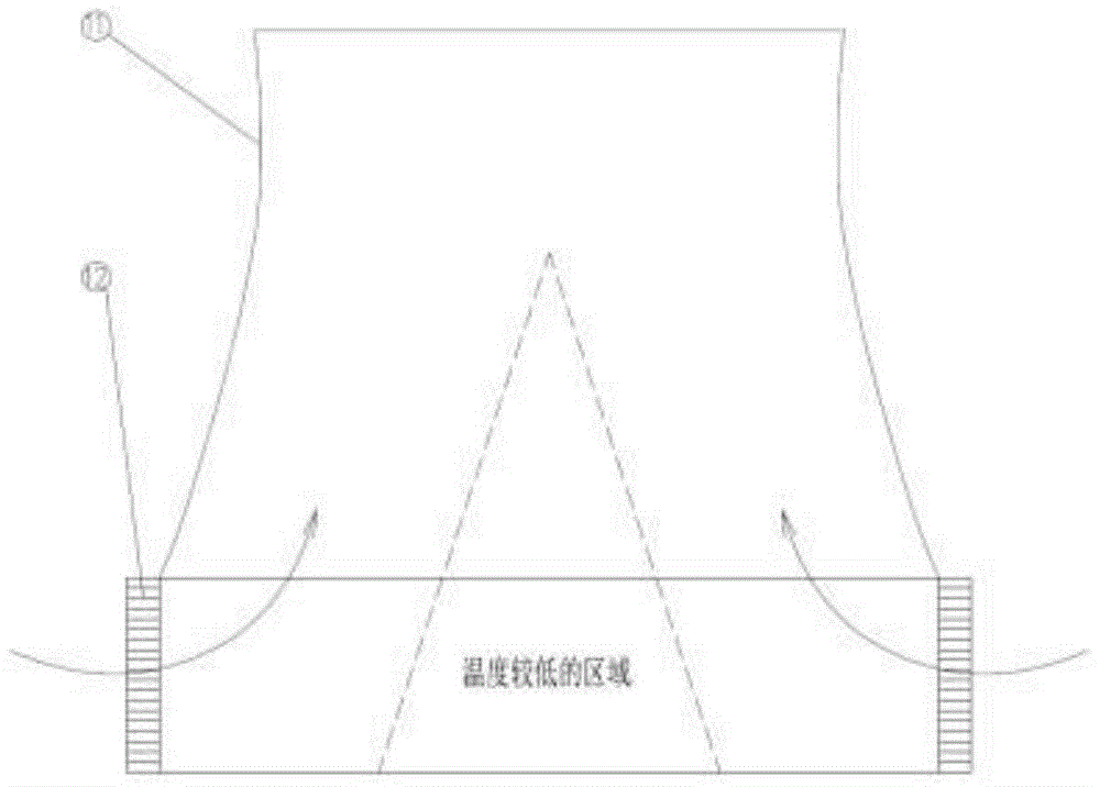
[0011] 2. The short and fat cooling tower only arranges cooling triangles around the bottom of the tower, which does not make full use of the inner area of ​​the tower, and the heat exchange area arranged is too small
When the ambient wind speed is high, drafts will be formed, which will affect the heat transfer effect

Method used


Image

  • Indirect cooling tower with cooling triangles arranged obliquely
  • Indirect cooling tower with cooling triangles arranged obliquely
  • Indirect cooling tower with cooling triangles arranged obliquely

Examples


Embodiment 1

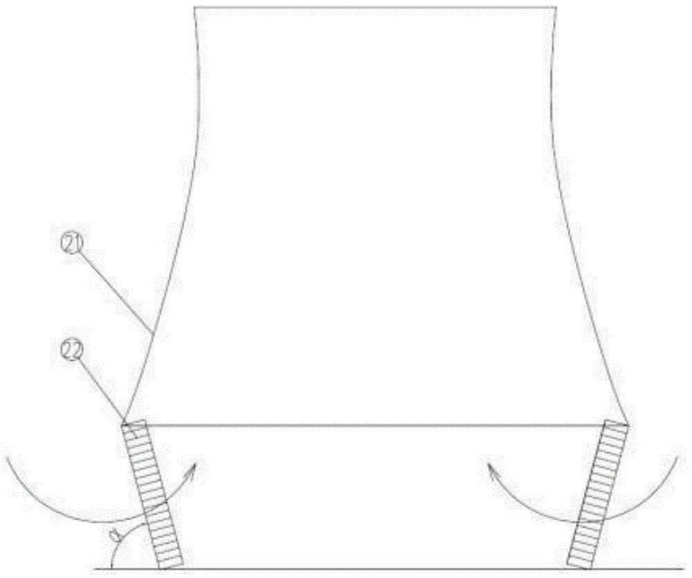
[0041] Such as figure 2 Shown is an indirect cooling tower structure with an inclined cooling triangle, which is composed of a tower tube 21 and an inclined cooling triangle 22 .

[0042] The angle between the cooling triangle 22 and the ground is α=40-75°,

[0043] The cooling triangle 22 is located at the inner edge of the bottom diameter of the intercooling tower barrel 21 .

[0044] Compared with the current vertically arranged cooling triangle, the adoption of the above structure leads to:

[0045] 1. When the height of the air inlet and the diameter of the bottom of the tower remain unchanged, the heat dissipation area of ​​the inclined cooling triangle is larger than that of the vertical cooling triangle, the water temperature at the outlet of the cooling tower is lowered, and the power supply coal consumption of the power plant is reduced.

[0046] 2. When the heat dissipation area and the height of the air inlet remain unchanged, the diameter of the bottom of the t...

Embodiment 2

[0049] Figure 4 It is an intercooling tower with segmented oblique cooling triangles, which is composed of a tower tube 31 and segmented oblique cooling triangles 32. The structural diagram of the segmented oblique cooling triangles 32 is as follows Figure 5 shown.

[0050] The segmented inclined cooling triangle 32 is composed of 3 to 10 small cooling triangles, each of which has independent water inlet and outlet pipelines and valves, which can be switched on and off independently.

[0051] The highest section of the small cooling triangle is perpendicular to the inner wall of the tower, and the angle β between the lowest section of the small cooling triangle and the ground is 75-90°.

[0052] The angle α formed by the top of the highest section of small cooling triangle and the bottom of the lowest section of small cooling triangle is 40-75°.

[0053] For the convenience of processing, all the small cooling triangles have the same length, and the included angles between...


PUM


Abstract

The invention discloses an indirect cooling tower with cooling triangles arranged obliquely, and particularly relates to an indirect cooling tower with cooling triangles arranged obliquely and segmented cooling triangles arranged obliquely. The indirect cooling tower comprises an indirect cooling tower drum and the cooling triangles arranged obliquely. After the structure is adopted, the indirect cooling tower has the following advantages that under the condition of the same diameter of the tower drum, the heat dissipation area can be increased; on the premise of ensuring the same heat dissipation area, the diameter of the tower drum of the cooling tower can be greatly reduced, occupied area and construction investment can be reduced, and the natural circulation power of the cooling tower can be increased; it can be effectively avoided that cross ventilation occurs in a crosswind environment to reduce the cooling efficiency; a temperature field and a flow field in the tower are more uniform.

Description

technical field [0001] The invention relates to the field of energy and power engineering, in particular to an indirect cooling tower with an inclined cooling triangle Background technique [0002] On September 12, 2014, the National Development and Reform Commission issued a notice on the "Coal Power Energy Conservation and Emission Reduction Upgrading and Transformation Action Plan (2014-2020)", which clearly stipulates the power supply that must be achieved by various coal power units in 2020. Coal consumption indicators, coal power units are under great pressure to save energy. [0003] The indirect cooling tower (hereinafter referred to as the indirect cooling tower) is located at the cold end of the thermodynamic cycle of the air-cooling unit, and its working performance directly affects the vacuum of the condenser and the coal consumption of power supply. The data shows that every time the water temperature at the outlet of the cooling tower decreases by 1°C, the vac...

Claims


Application Information

Patent Timeline
Patent Type & Authority Applications(China)
IPC IPC(8): F28C1/14
Inventor 史月涛高明孙奉仲赵元宾
Owner SHANDONG UNIV
Learn More