
Tunnel boring machine rock breaking seismic source and active source three-dimensional seismic combined advanced detection system

A technology of tunnel boring machine and 3D seismic, which is applied in seismology, seismic energy generation, geophysical measurement, etc. It can solve problems affecting construction progress, single source sensor, misreporting and misreporting, etc., and achieve rapid layout, 3D full The effect of spatial flexibility

Active Publication Date: 2015-06-03
山东百廿慧通工程科技有限公司
View PDF6 Cites 32 Cited by
  • Summary
  • Abstract
  • Description
  • Claims
  • Application Information

AI Technical Summary

Problems solved by technology

[0005] ②The tunnel boring machine is bulky and occupies most of the tunnel space behind the working face, resulting in a very narrow observation space for advanced geological exploration;
[0008] ①The BEAM (Bore-Tunneling Electrical Ahead Monitoring) system launched by the German Geohydraulic Data Company, BEAM is a one-dimensional focus-like excited polarization method, which has a short detection distance and is greatly affected by electromagnetic interference, and the installation of test equipment is complicated and time-consuming Longer, affecting the construction progress;
[0009] ②Seismic wave advanced detection methods such as SSP (Sonic Softground Probing) and ISIS (Integrated Seismic Imaging System) have relatively simple observation methods and do not use effective three-dimensional space observation methods, resulting in poor spatial positioning of anomalies and unsatisfactory spatial resolution;
[0010] ③ Domestic invention patents "A Geological Advance Forecasting Method Suitable for TBM Construction" and "Device-While-drilling Seismic Advance Detection Device and Method Using TBM as Vibration Source" refer to the seismic-while-drilling method in petroleum logging, and propose the use of rock The cutting signal is used as the seismic source for advanced geological detection. The former basically follows the HSP processing method in the drilling and blasting tunnel, and does not take appropriate denoising methods for the strong interference noise of the rock-breaking vibration of the roadheader, while the latter is mainly aimed at mines. The more commonly used cantilever roadheader in the roadway, the cantilever roadheader has only one cutting head, and there is only one seismic source signal receiving sensor on the roadheader arm behind the cutting head. Compared with it, the tunnel boring machine has a huge cutterhead area Moreover, there are a large number of rock-breaking hobs, and the rock-breaking vibrations of different hobs are very different. It is difficult to obtain accurate and comprehensive rock-breaking vibration characteristics with only a single sensor.
[0012] ① The spatial layout of the receiving sensors is simple, and no effective three-dimensional space observation method is adopted, so it is difficult to obtain more accurate three-dimensional wave field information of the surrounding rock mass, resulting in poor spatial positioning of abnormal bodies, and prone to omissions, misreports and false positives. report and other issues;
[0013] ② With regard to the active source seismic method, in order not to affect the normal construction of the tunnel boring machine, it is necessary to make use of the maintenance time of the tunnel boring machine for detection as much as possible. The existing method lacks a fast installation device and method specially for the tunnel boring machine construction tunnel, resulting in low detection efficiency. Low, affecting the normal construction of the roadheader;
[0014] ③ With regard to the rock-breaking source seismic method, on the one hand, it does not consider the difference between the rock-breaking method of the cutter head of the roadheader and the single-head rock-breaking method of the cantilever roadheader used in oil drilling and coal mines, that is, the cutter head of the tunnel boring machine has a large area and is used for There are a large number of rock-breaking hobs, and the rock-breaking vibrations between different hobs are very different. However, the existing method only uses a single source sensor, and it is difficult to obtain accurate and comprehensive rock-breaking vibration characteristics. On the other hand, the existing The processing method does not perform special noise removal for the source signal and the received signal, which makes the signal-to-noise ratio of the seismic record low and affects the detection accuracy;
[0015] ④ The active source seismic method uses an air hammer or a magnetostrictor to strike the tunnel side wall or working face to generate seismic waves during the downtime of the roadheader. The shock energy is relatively strong, which is suitable for long-distance advanced detection. Using the rock-breaking vibration of the cutter head during the working process of the roadheader as the seismic source, the shock energy is relatively weak but contains a high proportion of shear wave components, which has advantages in short-distance and more accurate detection. These two methods have advantages in working time and detection distance. They are highly complementary, and the organic combination of the two methods can further improve the accuracy and reliability of the advance prediction results of the seismic method, but the existing technology has not been able to combine the two well

Method used


Image

  • Tunnel boring machine rock breaking seismic source and active source three-dimensional seismic combined advanced detection system
  • Tunnel boring machine rock breaking seismic source and active source three-dimensional seismic combined advanced detection system
  • Tunnel boring machine rock breaking seismic source and active source three-dimensional seismic combined advanced detection system

Examples


Embodiment Construction

[0078] The present invention will be further described below in conjunction with the accompanying drawings and embodiments.

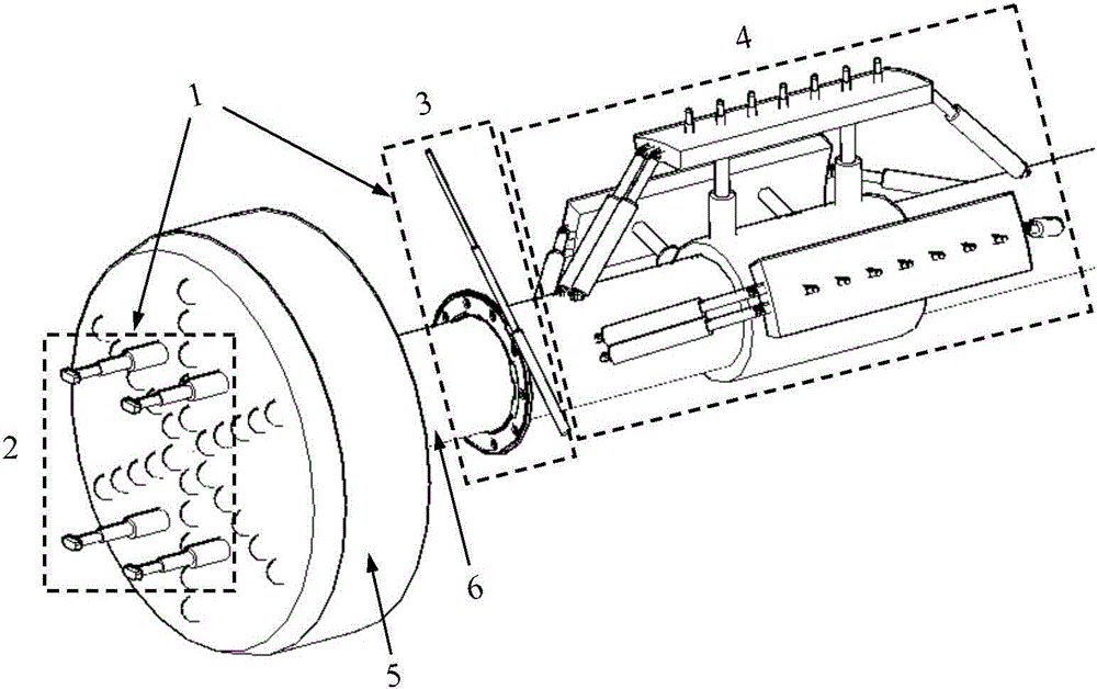
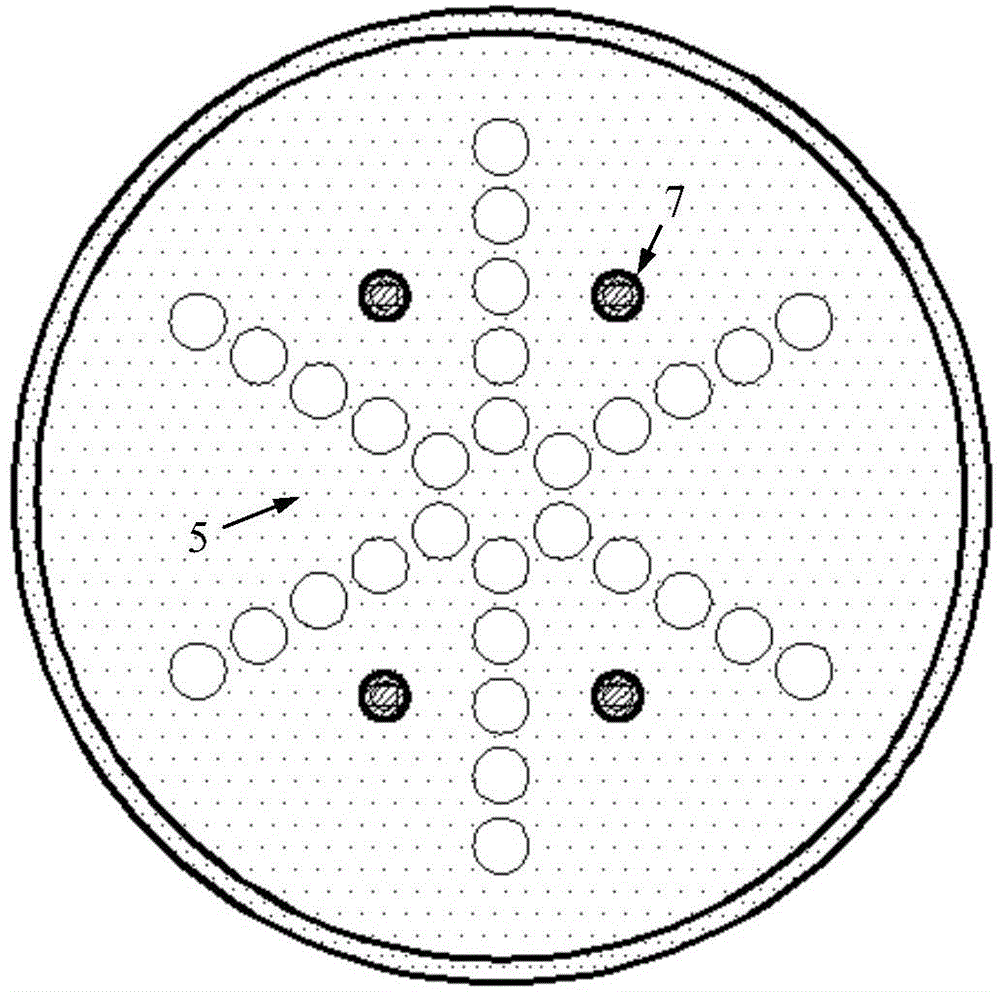
[0079] Such as figure 1 As shown, a three-dimensional seismic joint advanced detection method and device for active source and rock-breaking seismic source in complex environment of roadheader tunnel, mainly including shock system 1, receiving sensor and its supporting device 4, rock-breaking source sensor array, roadheader Working noise sensor, control system, and multi-channel seismic wave data acquisition instrument.

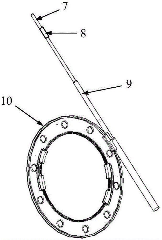
[0080] The shock system is divided into a working face source 2 and a side wall source 3 according to different positions. The working face source 2 includes a vibrator 7, a source pressure sensor 8, a source hydraulic telescopic rod 9 and a source inlet and outlet hatch. The side wall seismic source includes a vibrator 7 , a seismic source pressure sensor 8 , a seismic source hydraulic expansion rod 9 and a seismic source guide rail ...


PUM


Abstract

The invention discloses a tunnel boring machine rock breaking seismic source and active source three-dimensional seismic combined advanced detection system. The system comprehensively utilizes two modes of active source seismic source and rock breaking seismic source to perform three-dimensional seismic combined advanced detection, adopts an active source seismic method with high shock energy to realize long distance advanced prediction and positioning recognition of geological anomalous bodies before operation of a tunnel boring machine, performs adjustment and optimization on the following construction of the tunnel boring machine according to a detection result, adopts cutterhead rock breaking vibration with weak shock energy and high ratio of transverse wave components as a seismic source, adopts an unconventional rock breaking seismic source seismic record processing method to realize the real-time short-distance accurate prediction of the geological anomalous bodies, performs representation and evaluation on the quality of surrounding rock in a region to be excavated, finally comprehensively judges the geological condition of a part in front of a working surface according to combined results of active source and rock break seismic source three-dimensional seismic advanced detection, and provides a support for the optimization of tunnel boring machine operating parameters and construction safety control.

Description

technical field [0001] The invention relates to a three-dimensional seismic joint advance detection system of a rock-breaking seismic source and an active source of a tunnel boring machine. Background technique [0002] Tunnel construction usually adopts full-face tunnel boring machine construction and drill-and-blast method. Compared with the traditional drill-and-blast method, tunnel boring machine construction has significant advantages such as high degree of mechanization and fast construction speed. Developed countries such as Japan, the United States, and Europe use roadheaders. The proportion of tunnels under construction exceeds 80%, and with the continuous development of tunnel construction in China, tunnel boring machines will also be used more and more. Numerous engineering practices have shown that tunnel boring machines have poor adaptability to changes in geological conditions. Geological disasters such as water and mud inrush and landslides often occur when en...

Claims


Application Information

Patent Timeline
IPC IPC(8): G01V1/00G01V1/02G01V1/20
Inventor 李术才刘斌许新骥宋杰聂利超杨磊林春金杨为民
Owner 山东百廿慧通工程科技有限公司
Learn More