
A Servo Motor Control Method Combining Sliding Mode Control and Fractional Neural Network Control

A neural network control and servo motor technology, applied in the control of generators, motor generator control, electronic commutation motor control, etc., can solve the problem that sliding mode control technology no longer has strong robustness, affects system tracking performance, and system Tremor and other issues

Active Publication Date: 2017-05-03
GUANGZHOU HKUST FOK YING TUNG RES INST
View PDF2 Cites 0 Cited by
  • Summary
  • Abstract
  • Description
  • Claims
  • Application Information

AI Technical Summary

Problems solved by technology

However, the high-frequency switching of sliding mode control will cause system chatter, which will affect the tracking performance of the system
[0004] Aiming at the chattering problem existing in sliding mode control technology, the current popular treatment method is the positive lateralization method, that is, using a saturation function instead of a switching function, but this method makes the sliding mode control technology no longer have strong robustness

Method used


Image

  • A Servo Motor Control Method Combining Sliding Mode Control and Fractional Neural Network Control
  • A Servo Motor Control Method Combining Sliding Mode Control and Fractional Neural Network Control
  • A Servo Motor Control Method Combining Sliding Mode Control and Fractional Neural Network Control

Examples


Embodiment 1

[0115] In this embodiment, a permanent magnet synchronous motor is taken as an example to describe the implementation process of the present invention. The control method of the permanent magnet synchronous motor in this embodiment includes the following four steps:

[0116] (1) Describe the permanent magnet synchronous motor model

[0117] The mathematical model of the permanent magnet synchronous motor in the rotating coordinate system is:

[0118]

[0119] The corresponding electromagnetic torque equation is:

[0120]

[0121] The corresponding kinetic equation is:

[0122]

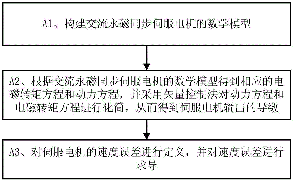
[0123] By applying vector control, the dynamic equation (3) can be simplified as:

[0124]

[0125] Substituting the dynamic equation (4) into the electromagnetic torque equation (2), we can get:

[0126]

[0127] Considering the change of motor parameters, the above formula can be expressed as:

[0128]

[0129] The purpose of controller design is to find a suitable control law so...

no. 2 example

[0183] The control method proposed by the invention has been successfully applied to the speed loop of the permanent magnet synchronous motor drive system. The structure of the speed loop of the permanent magnet synchronous motor drive system is composed of speed controller, coordinate transformation module, pulse width speed regulation module, inverter, permanent magnet synchronous motor (PMSM) and encoder and other modules, such as Figure 5 shown.

[0184] The speed loop controller is implemented on TI's dsp chip stm320f2812. The servo motor is a Japanese Sanyo permanent magnet synchronous motor (PMSM), with a power of 1kw and a rated speed of 1000r / min. The load disturbance outside the system is simulated by changing the load of the motor.

[0185] The specific algorithm and control flow of the speed loop of the permanent magnet synchronous motor drive system are as follows: Figure 6 and Figure 7 As shown, the sinusoidal tracking result of the speed loop of the permane...


PUM


Abstract

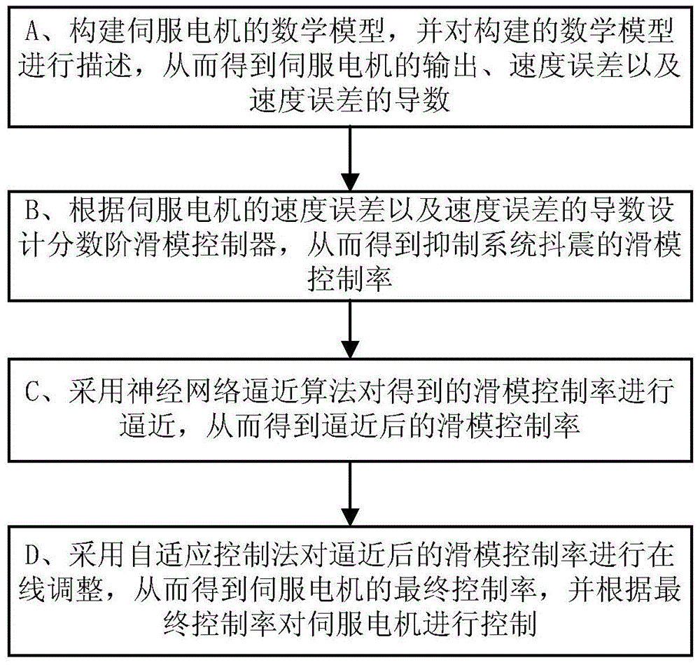
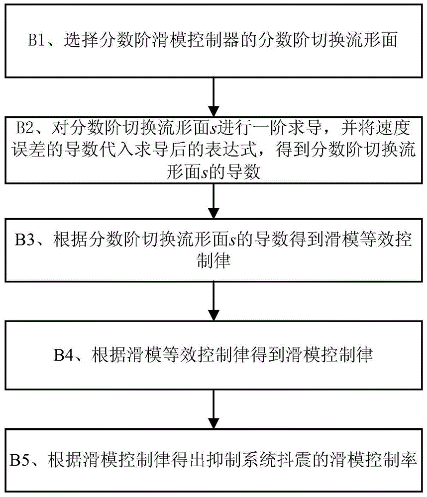
The invention discloses a servo motor control method integrating sliding mode control and fractional order neural network control. The servo motor control method comprises the following steps of A, establishing a numerical model of a servo motor, and describing the numerical model of the servo motor, so as to obtain the output, speed error and speed error derivative of the servo motor; B, according to the speed error and the speed error derivative of the servo motor, designing a fractional order sliding mode controller, so as to obtain a sliding mode control rule for inhibiting the buffet of the system; C, adopting a neutral network approximating algorithm to approximate the obtained sliding mode control rule, so as to obtain the approximated sliding mode control rule; D, adopting a self-adaptive control method to adjust the approximated sliding mode control rule on line, so as to obtain a final control rule of the servo motor; according to the final control rule, controlling the servo motor. The servo motor control method has the advantages that the sliding mode control theory and the fractional order neural network adaptive control theory are integrated, the robustness is high, and the tracking property is good; the servo motor control method can be widely applied to the field of industrial control.

Description

technical field [0001] The invention relates to the field of industrial control, in particular to a servo motor control method which combines sliding mode control and fractional neural network control. Background technique [0002] PID controller has the characteristics of simplicity and easy operation, so that more than 80% of permanent magnet synchronous AC servo motors are controlled by PID control algorithm. However, in the case of time-varying system parameters and external disturbances, the PID control algorithm will have problems such as divergence, which will seriously affect the control performance of the system, making it unsuitable for applications requiring high precision. [0003] In view of the weak robustness of the traditional PID control algorithm to the time-varying system parameters and external disturbances, the currently popular control method is the sliding mode control technology. As long as the time-varying parameters of the system and external distu...

Claims


Application Information

Patent Timeline
Patent Type & Authority Patents(China)
IPC IPC(8): H02P21/00
Inventor 张碧陶高福荣姚科
Owner GUANGZHOU HKUST FOK YING TUNG RES INST
Learn More