
Rotary drilling rig main winch system based on energy recovery of energy accumulator

An energy recovery, rotary drilling rig technology, applied in the direction of winch, spring mechanism, fluid pressure actuation system components, etc., can solve problems such as reducing the service life of hydraulic components, consuming large engine power, and increasing system heat load. , to achieve the effect of improving energy utilization, reducing heat loss and reducing load

Inactive Publication Date: 2015-05-06
CHANGAN UNIV
View PDF9 Cites 10 Cited by
  • Summary
  • Abstract
  • Description
  • Claims
  • Application Information

AI Technical Summary

Problems solved by technology

[0003] Energy consumption analysis of the main hoisting system of the existing rotary drilling rig: when the rotary drilling rig is working, the drill rod and drilling tools need to be lifted and lowered repeatedly. The pump drives the main hoisting motor to rotate, and the main hoisting motor drives the hoisting mechanism to lift the drilling tool and the drill pipe. Due to the high quality of the drill pipe, drilling tool and the soil inside the drilling tool, the lifting stroke is as long as tens of meters deep. It needs to consume a lot of engine power. During the lifting operation, the hydraulic energy is converted into the gravitational potential energy of the drill pipe and drilling tools through the lifting action of the main winch motor; output power, and the drill pipe and drilling tools release a large amount of gravitational potential energy, which is basically consumed on the orifice of the balance valve, causing the system to heat up, increasing the thermal load of the system, and reducing the service life of the hydraulic components. while wasting energy

Method used


Image

  • Rotary drilling rig main winch system based on energy recovery of energy accumulator
  • Rotary drilling rig main winch system based on energy recovery of energy accumulator
  • Rotary drilling rig main winch system based on energy recovery of energy accumulator

Examples


Embodiment 1

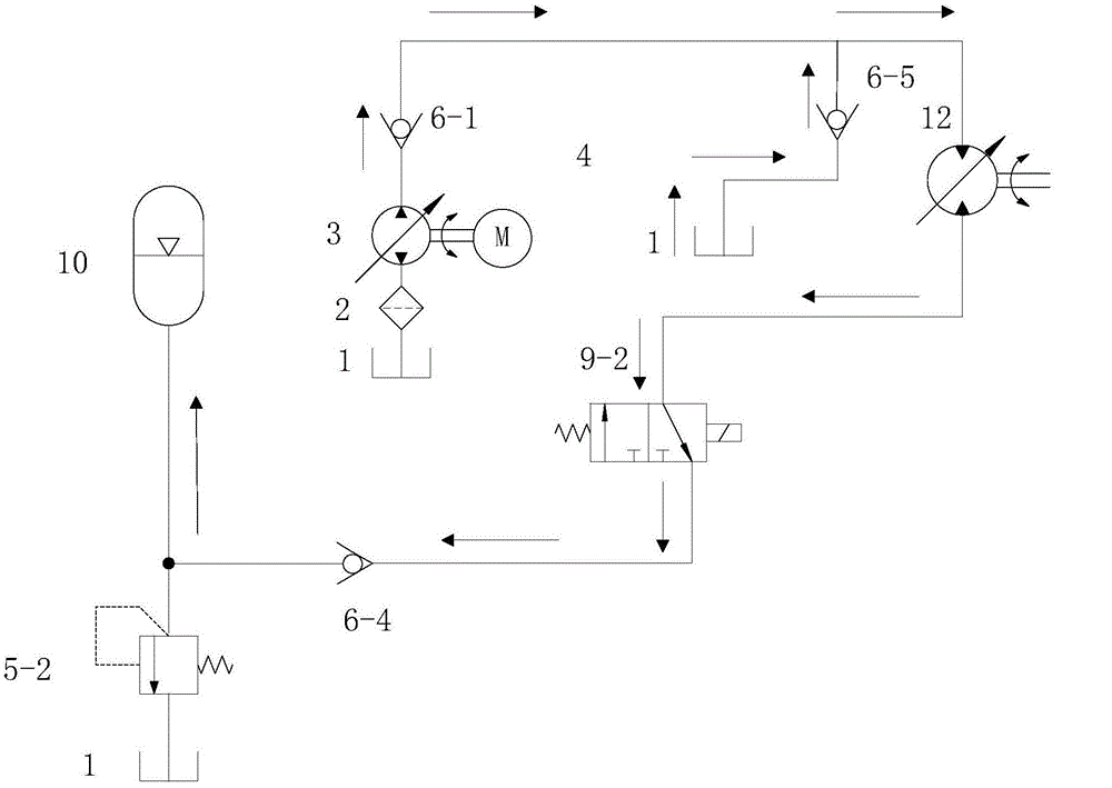
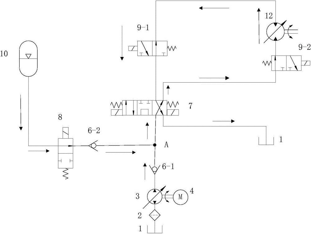
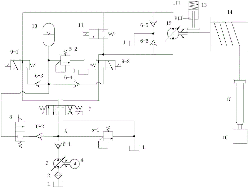
[0021] see image 3 , the present invention includes motor 4, hydraulic pump 3, oil filter 2, oil tank 1, accumulator 10, main winch motor 12, brake cylinder 13, reel 14, drill pipe 15, drilling tool 16, first overflow Flow valve 5-1 and second overflow valve 5-2, float valve 11, confluence valve 8, main electromagnetic reversing valve 7, first energy recovery valve 9-1 and second energy recovery valve 9-2 and first One-way valve 6-1, second one-way valve 6-2, third one-way valve 6-3, fourth one-way valve 6-4, fifth one-way valve 6-5 and sixth one-way valve 6- 6. The main electromagnetic reversing valve 7 is sequentially connected to the first one-way valve 6-1, the first energy recovery valve 9-1, the second energy recovery valve 9-2, and the first fuel tank 1-1; the accumulator 10 is sequentially Connected to the second overflow valve 5-2, the third one-way valve 6-3, the fourth one-way valve 6-4, the confluence valve 8; the first energy recovery valve 9-1 and the second en...


PUM


Abstract

The invention discloses a rotary drilling rig main winch system based on energy recovery of an energy accumulator. Under a down-pass working condition, a hydraulic pump outputs hydraulic energy to drive a main winch motor to rotate reversely so as to drive a drill stem of a drill rig to fall off, the main winch motor is driven to rotate by virtue of the falling inertia, the rotation speed of the main winch motor is quickened, the oil supply speed of the hydraulic pump can not keep pace with the rotation speed of the motor, the oil inlet of the motor is locally vacuum, the main winch motor is equivalent to the pump at the moment, and high-pressure oil is output so as to charge energy for the energy accumulator by virtue of an energy recovery valve, which is equivalent to the fact that two hydraulic pumps store energy into the energy accumulator at the moment, so that gravitational potential energy recovery is realized. The energy recovery route is as follows: the gravitational potential energy recovery of a drill stem of the drill jig is converted into hydraulic energy by virtue of the main winch motor, and the hydraulic energy is stored in the energy accumulator and used for a lifting working condition. According to the rotary drilling rig main winch system, the gravitational potential energy is recovered, heat losses are reduced, the heat load of the system is reduced, and the service life of a hydraulic component is prolonged.

Description

technical field [0001] The invention belongs to the field of construction machinery equipment, and in particular relates to a main winch system of a rotary drilling rig based on the energy recovery of an accumulator. Background technique [0002] In the 21st century when resources are scarce, the pursuit of high efficiency and low energy consumption has always been an important goal of domestic and foreign manufacturing industries. Rotary drilling rigs are piling equipment in construction machinery and are widely used in construction. Reducing the energy consumption of rotary drilling rigs is of great significance to saving energy. [0003] Energy consumption analysis of the main hoisting system of the existing rotary drilling rig: when the rotary drilling rig is working, the drill rod and drilling tools need to be lifted and lowered repeatedly. The pump drives the main hoisting motor to rotate, and the main hoisting motor drives the hoisting mechanism to lift the drilling ...

Claims


Application Information

Patent Timeline
IPC IPC(8): F15B21/14B66D1/08
CPCF15B21/14B66D1/08
Inventor 焦生杰徐信芯熊玉龙张鹏程
Owner CHANGAN UNIV
Learn More