Medium or small-sized boiler exhaust gas plasma de-nitrating method
A technology of plasma and boiler exhaust gas, which is applied in the field of plasma denitrification to achieve high safety, high denitrification efficiency, and the effect of eliminating hidden dangers of explosion
- Summary
- Abstract
- Description
- Claims
- Application Information
AI Technical Summary
Problems solved by technology
Method used
Image
Examples
Embodiment 1
[0040] Example 1 A plasma denitration method for waste gas from small and medium-sized boilers
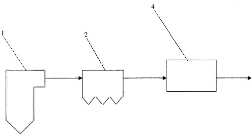
[0041] The exhaust gas discharged from the boiler contains NO, which is mixed with reducing gas by a static mixer, and the above-mentioned mixed gas is brought into the electrode zone or the reaction zone behind the electrode zone in the plasma reaction vessel. In this zone, the NO in the exhaust gas is Reducing gas is reduced to N 2 And CO 2 And water and other harmless gases. The reducing gas can undergo a reduction reaction with NO under the action of plasma, and is preferably one of hydrogen, chlorine, carbon monoxide, hydrogen sulfide, methane, sulfur dioxide, ozone, propylene, ethylene, hydrogen bromide or hydrogen iodide. One or more mixed gases.
Embodiment 2
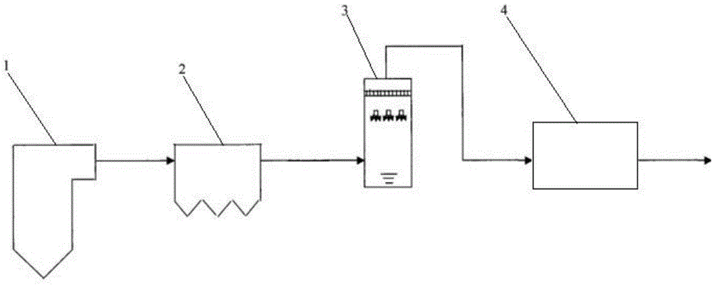
[0043] The exhaust gas discharged from the boiler is cooled and dust removed, so that the temperature of the exhaust gas is lower than 80°C, and then the above exhaust gas is mixed with the reducing gas and brought into the electrode zone in the plasma reaction vessel or the reaction zone behind the electrode zone. In this area, NO in exhaust gas is reduced to N 2 And CO 2 And water and other harmless gases. The NOx removal efficiency can be further improved by controlling the addition ratio of the exhaust gas and the reducing gas, and it is preferable that the ratio of the number of molecules of the reducing gas to NO is 1:2-5.
Embodiment 3
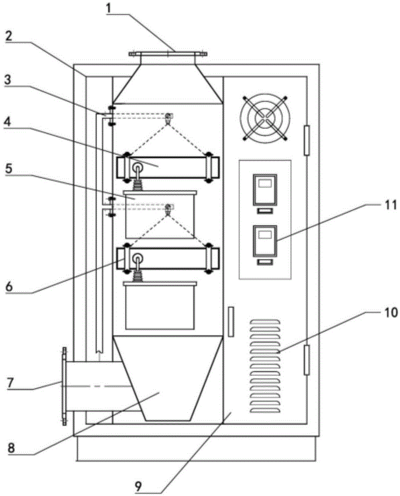
[0045] The exhaust gas discharged from the boiler contains NO, which is mixed with reducing gas by a static mixer, and the above-mentioned mixed gas is brought into the electrode zone or the reaction zone behind the electrode zone in the plasma reaction vessel. In this zone, the NO in the exhaust gas is Reduce to N 2 And CO 2 And water and other harmless gases. The said plasma reaction vessel uses the principle of dielectric barrier discharge. Under the action of high-energy electrons, charged particles are formed or the chemical bonds between molecules are broken to generate active particles such as free radicals. The entire discharge is composed of many randomly distributed in space and time. The micro-discharge composition of the micro-discharge, the duration of these micro-discharges is very short, generally on the order of 10ns. The dielectric layer has two main functions for this type of discharge: one is to limit the movement of charged particles in the microdischarge, s...
PUM
 Abstract
Description
Claims
Application Information
 - Generate Ideas
- Intellectual Property
- Life Sciences
- Materials
- Tech Scout
- Unparalleled Data Quality
- Higher Quality Content
- 60% Fewer Hallucinations
Browse by: Latest US Patents, China's latest patents, Technical Efficacy Thesaurus, Application Domain, Technology Topic, Popular Technical Reports.
© 2025 PatSnap. All rights reserved.Legal|Privacy policy|Modern Slavery Act Transparency Statement|Sitemap|About US| Contact US: help@patsnap.com


