Particle carrier impregnation method
A carrier and particle technology, applied in chemical instruments and methods, catalyst activation/preparation, other chemical processes, etc., can solve the problem that the wear strength of the catalyst needs to be improved, and achieve the effect of ensuring the particle size distribution and strength of the carrier, and good wear performance
- Summary
- Abstract
- Description
- Claims
- Application Information
AI Technical Summary
Problems solved by technology
Method used
Image
Examples
Embodiment approach
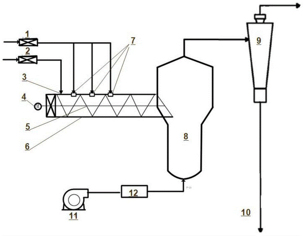
[0105] Figure 3 to Figure 8 A first preferred embodiment of the invention is shown. Figure 3 to Figure 8 The reference signs in include: impregnation liquid delivery system 1, particle carrier feeding system 2, particle carrier inlet 3, power system 4, transmission shaft 5, mixing conveyor 6, impregnation liquid nozzle 7, dryer 8, Separator 9 , impregnated carrier line 10 , conveyor belt 1125 , fan 1234 , air distribution plate 1235 .
[0106] Such as Figure 3 to Figure 8 As shown, the impregnation equipment includes a particle carrier inlet, an immersion liquid nozzle, a mixing conveyor and a dryer, wherein the outlet of the mixing conveyor is connected to the dryer, and the particle carrier inlet is connected to the mixing conveyor The impregnating liquid nozzle is communicated with the mixing conveyor, and the impregnating liquid nozzle is located between the inlet of the particle carrier and the outlet of the mixing conveyor; the device also includes a Conveying devi...
Embodiment approach 1-1
[0117] The conveying device may be a transmission shaft (embodiment 1-1), a conveyor belt (embodiment 1-2) or a particle fluidization system (embodiment 1-3).
[0118] Embodiment 1-1:
[0119] The conveying device is a transmission shaft, and the transmission shaft is located in the mixing conveyor. The transmission shaft is driven by a power system including an electric motor. The transmission shaft in the mixer can be a threaded structure or a folded plate structure, preferably a folded plate structure. Preferably, the bottom of the mixing conveyor has a loose tuyere (not shown in the figure), which can reduce the wear and tear during the turning process of the particle carrier.
[0120] To facilitate delivery of the particulate carrier into the dryer, the mixing conveyor and the transfer shaft are sloped downward from the inlet of the particulate carrier to the outlet of the mixing conveyor. The inclination angle can be greater than 0 to 45°, preferably 10-30°.
Embodiment approach 1-2
[0122] The conveying device is a conveyor belt, and the conveyor belt is located in the mixing conveyor. The conveyor belt is driven by a power system including a motor. The conveyor belt is preferably mesh-shaped, that is, it is provided with a plurality of holes (not shown in the figure) as air outlets, which are used as loose air outlets for the carrier, and promote the uniform mixing of the carrier with the impregnating liquid during the transmission process. The conveying speed of the conveyor belt can be 0.5-8m / s, preferably 1-5m / s.
PUM
| Property | Measurement | Unit |
|---|---|---|
| The average particle size | aaaaa | aaaaa |
| Diameter | aaaaa | aaaaa |
Abstract
Description
Claims
Application Information
 - R&D
- Intellectual Property
- Life Sciences
- Materials
- Tech Scout
- Unparalleled Data Quality
- Higher Quality Content
- 60% Fewer Hallucinations
Browse by: Latest US Patents, China's latest patents, Technical Efficacy Thesaurus, Application Domain, Technology Topic, Popular Technical Reports.
© 2025 PatSnap. All rights reserved.Legal|Privacy policy|Modern Slavery Act Transparency Statement|Sitemap|About US| Contact US: help@patsnap.com


