
Automobile ignition module constant-current control circuit

A constant current control circuit and ignition module technology, applied in ignition controllers, spark ignition controllers, engine ignition, etc., can solve problems such as troublesome debugging, poor temperature characteristics, complex circuits, etc. Small number and good temperature characteristics

Active Publication Date: 2015-04-01
长沙奥斯凯汽车零部件有限公司
View PDF6 Cites 1 Cited by
  • Summary
  • Abstract
  • Description
  • Claims
  • Application Information

AI Technical Summary

Problems solved by technology

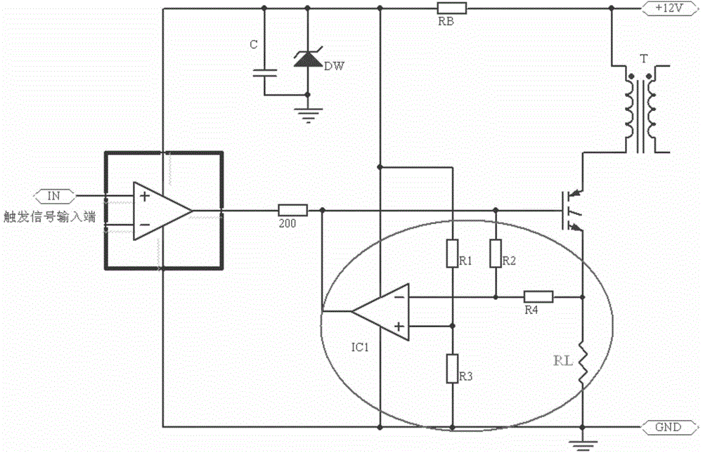
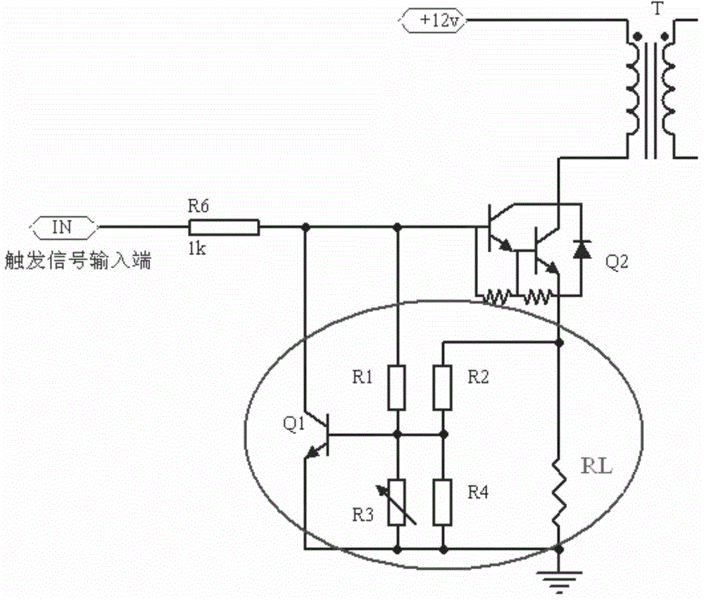
[0004] but figure 1 , 2 The traditional module constant current circuits shown have their own deficiencies, figure 1 The circuit is complex, there are many additional components, and debugging is also troublesome
And it can only be used in active module circuits, and cannot be used in passive modules
figure 2 The number of circuit components is large, the working stability is poor, and the temperature characteristics are poor. Although the temperature compensation component is set, it still cannot achieve the ideal constant current effect.

Method used


Image

  • Automobile ignition module constant-current control circuit
  • Automobile ignition module constant-current control circuit
  • Automobile ignition module constant-current control circuit

Examples


Embodiment Construction

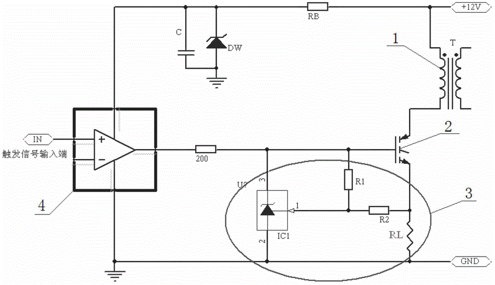
[0015] see image 3 , 4 , reflecting a specific application structure of the present invention. The shown constant current circuits all include an ignition coil 1 , a switching power tube 2 , and a constant current control circuit 3 , and the active module constant current circuit is also provided with a signal processing circuit 4 . The constant current control circuit 3 is composed of a three-terminal programmable voltage regulator IC1, programming resistors R1, R2, and current sampling resistor RL: the cathode of the three-terminal programmable voltage regulator is connected to the base of the switching power tube (control pole ), the reference end of the three-terminal programmable voltage regulator tube is connected to the voltage dividing point composed of programming resistors R1 and R2; the other end of the resistor R1 is connected to the base of the switching power tube, and the other end of the resistor R2 is connected to the current sampling resistor RL; the three-...


PUM


Abstract

The invention discloses a novel scheme of electronic circuit design and application. The invention has the core contents that a common three-end adjustable voltage stabilizing device is applied to a constant-current circuit of an automobile ignition module and the obtained product is matched with a small amount of passive devices to replace a conventional automobile ignition module constant-current circuit so as to enable the circuit to be more simple and reliable; in the working process, the constant-current performance is more stable and the temperature characteristic is better. The scheme can be used for various types of ignition module constant-current control circuits and also can be suitable for ignition module circuits of which the output levels adopt power tubes (darlington tubes or IGBT ((Insulated Gate Bipolar Transistor)) with different characteristics.

Description

technical field [0001] The invention relates to an electronic circuit design. Background technique [0002] There are two common forms of traditional ignition module constant current control circuits: (1) active module constant current circuit, generally controlled by a comparator (see figure 1 ); (2) Passive module constant current circuit, generally controlled by triode (see figure 2 ). [0003] The parts of the constant current control circuit of the above two forms are shown in the circled part in the figure. The control principles are basically the same. When there is a trigger high-level signal at the input terminal, the output switching power tube is turned on, and the conduction current generates a sampling voltage on the current sampling resistor RL. When the voltage reaches the set value, the core component of the constant current control part ( figure 1 IC1 in figure 2 The working state of Q1) begins to change from the original cut-off state to the on-state...

Claims


Application Information

Patent Timeline
Patent Type & Authority Applications(China)
IPC IPC(8): F02P9/00
CPCF02P9/00
Inventor 康贤清
Owner 长沙奥斯凯汽车零部件有限公司
Learn More