
Method for manufacturing embedded source/drain MOS transistors

A technology of MOS transistors and manufacturing methods, which is applied in the field of manufacturing embedded source/drain MOS transistors, can solve problems such as high manufacturing costs, cumbersome steps, and expensive lithography costs, and achieve saving lithography steps, simplifying process steps, The effect of reducing manufacturing costs

Inactive Publication Date: 2015-03-25
SEMICON MFG INT (SHANGHAI) CORP
View PDF9 Cites 1 Cited by
  • Summary
  • Abstract
  • Description
  • Claims
  • Application Information

AI Technical Summary

Problems solved by technology

[0018] It can be seen that the existing manufacturing methods of CMOS devices with e-SiGe source / drain and e-SiC source / drain need to etch the silicon substrate at least twice to form the e-SiGe source respectively. / drain grooves and grooves for e-SiC source / drain electrodes, and each time in order to form one of the grooves, multiple steps are required, especially in the removal of photoresist and barrier layer. process steps, the lithography used is extremely expensive
Therefore, the above-mentioned manufacturing method not only has cumbersome steps, but also has extremely high manufacturing costs.

Method used


Image

  • Method for manufacturing embedded source/drain MOS transistors
  • Method for manufacturing embedded source/drain MOS transistors
  • Method for manufacturing embedded source/drain MOS transistors

Examples


Embodiment Construction

[0041] In order to make the above objects, features and advantages of the present invention more comprehensible, specific implementations of the present invention will be described in detail below in conjunction with the accompanying drawings.

[0042] In the following description, numerous specific details are set forth in order to provide a thorough understanding of the present invention. However, the present invention can be implemented in many other ways different from those described here, and those skilled in the art can make similar extensions without violating the connotation of the present invention, so the present invention is not limited by the specific implementations disclosed below.

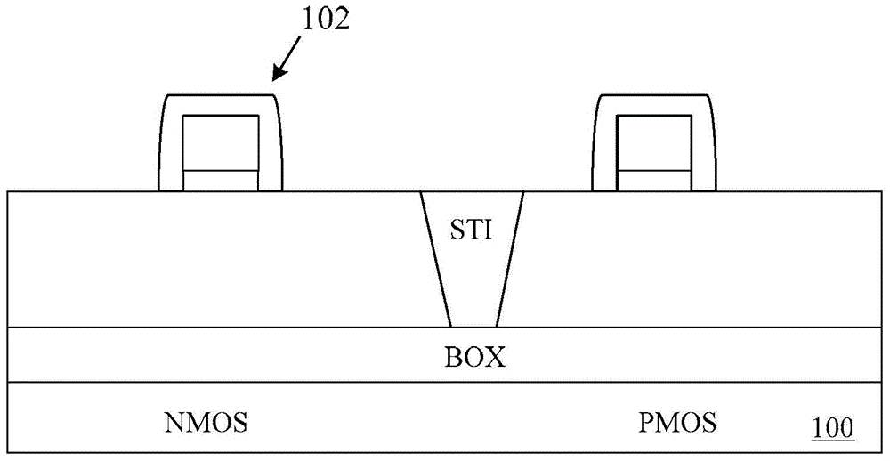
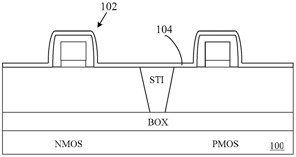
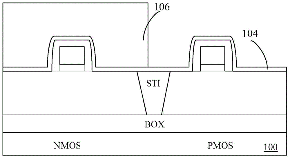
[0043] by figure 2 The manufacturing flow shown is an example, combined with Figure 3a to Figure 3f , a method for manufacturing an embedded source / drain MOS transistor provided by the present invention will be described in detail.

[0044] In step S1, see Figure 3a , providin...


PUM


Abstract

The invention provides a method for manufacturing embedded source / drain MOS transistors. The method comprises the steps that gate structures are formed on a PMOS transistor area and an NMOS transistor area formed on a semiconductor substrate respectively, and an STI is arranged between the PMOS transistor area and the NMOS transistor area; channels adjacent to the two sides of each gate structure are synchronously formed on the PMOS transistor area and the NMOS transistor area; after first strained silicon grows in the channels of the PMOS transistor area and the NMOS transistor area, first embedded source / drain electrodes are synchronously formed; a barrier layer is disposed on the PMOS transistor area; after acid gas is used for etching the first embedded source / drain electrode in the NMOS transistor area so that second strained silicon can grow in the channels in the totally exposed PMOS pipe area, second embedded source / drain electrodes are formed; the barrier layer disposed on the PMOS transistor area is removed. According to the method, the existing technological steps of manufacturing the embedded source / drain MOS transistors can be optimized, and manufacturing cost can also be lowered.

Description

technical field [0001] The invention belongs to the technical field of semiconductor integrated circuit manufacturing, and in particular relates to a manufacturing method of an embedded source / drain MOS transistor. Background technique [0002] CMOS devices have continued to shrink in size over the past few decades. In early semiconductor circuit technology, the channel length in CMOS devices was on the order of several microns. By the end of the 1990s, the size of CMOS devices continued to shrink, which greatly improved the performance of semiconductor circuits. In today's semiconductor circuit technology, this parameter has been reduced by dozens of times or even more than one hundred times. [0003] However, the reduction in the size of CMOS devices also brings some negative issues. For example, a smaller channel width increases the channel equivalent resistance. With the in-depth research on the piezoresistance effect of silicon materials, the industry has gradually ...

Claims


Application Information

Patent Timeline
Patent Type & Authority Applications(China)
IPC IPC(8): H01L21/336
CPCH01L29/66477H01L29/401H01L29/7845H01L29/7848H01L29/84
Inventor 禹国宾
Owner SEMICON MFG INT (SHANGHAI) CORP
Learn More