
Method for manufacturing terminal-strip-equipped electronic component and terminal-strip-equipped electronic component

A technology for electronic components and manufacturing methods, which is applied in capacitor manufacturing, electrical components, and fixed capacitor dielectrics, etc., can solve problems such as cracks in electronic components, terminal electrode peeling, etc. The effect of reducing residual stress

Active Publication Date: 2015-03-18
MURATA MFG CO LTD
View PDF7 Cites 15 Cited by
  • Summary
  • Abstract
  • Description
  • Claims
  • Application Information

AI Technical Summary

Problems solved by technology

However, there may be a problem that cracks may occur in the electronic component due to stress due to the difference in thermal expansion coefficient between the wiring board and the electronic component, or stress due to bending of the wiring board, or the terminal electrode may be removed from the electronic component. Terminal component main body stripping

Method used


Image

  • Method for manufacturing terminal-strip-equipped electronic component and terminal-strip-equipped electronic component
  • Method for manufacturing terminal-strip-equipped electronic component and terminal-strip-equipped electronic component
  • Method for manufacturing terminal-strip-equipped electronic component and terminal-strip-equipped electronic component

Examples


Embodiment Construction

[0041] Hereinafter, one embodiment according to the present invention will be specifically described with reference to the drawings.

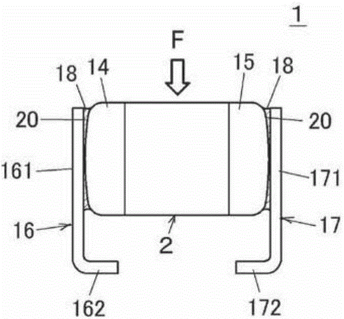
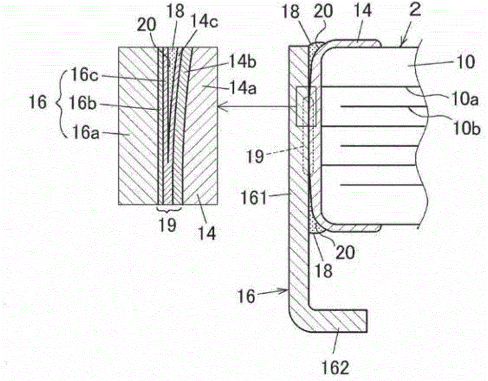
[0042] Such as figure 1 and figure 2 As shown, an electronic component 1 with a terminal board mounted thereon as an embodiment of the present invention includes an electronic chip component 2 and a pair of terminal boards 16 , 17 . The electronic component 2 includes a substantially rectangular parallelepiped ceramic body 10 . The ceramic body 10 includes, for example, a plurality of laminated ceramic layers and a plurality of internal electrodes 10a, 10b arranged between the ceramic layers. Since the structures and materials of the ceramic layers and internal electrodes are well known, description thereof will be omitted. In addition, as the electronic chip component 2, as long as it is a chip component with terminal electrodes formed on both end faces, for example, it may be a multilayer ceramic capacitor, a chip inductor, a chip thermist...


PUM


Abstract

A method for manufacturing a terminal-strip-equipped electronic component in which terminal strips made of a metal plate are bonded with solder to terminal electrodes of an electronic chip component on two opposing end surfaces. Solder cream is applied to outer surfaces of the terminal electrodes. The terminal strips are thermocompression bonded to the terminal electrodes by placing the electronic chip component between the terminal strips and pressing the terminal strips against the terminal electrodes using a pair of heating elements so as to obtain an electronic component to which the terminal strips are temporarily fixed. The terminal strips are fully fixed to the electronic component by melting the solder cream as a result of heating the electronic component in a heating furnace so as to obtain a terminal-strip-equipped electronic component.

Description

technical field [0001] The present invention relates to a bonding method for bonding a terminal board to an electronic chip component, and in particular to an improvement in a method for soldering a terminal board to a terminal electrode of an electronic component. Background technique [0002] For example, when mounting an electronic chip component such as a ceramic capacitor on a wiring board, a surface mount method in which terminal electrodes of the electronic component are directly soldered to lands on the wiring board is generally used. However, there may be a problem that cracks may occur in the electronic component due to stress due to the difference in thermal expansion coefficient between the wiring board and the electronic component, or stress due to bending of the wiring board, or the terminal electrode may be removed from the electronic component. The main body of the terminal component is peeled off. [0003] In order to solve such a problem, the following met...

Claims


Application Information

Patent Timeline
IPC IPC(8): H01G13/00H01G2/06
CPCH01G4/30B23K2201/42B23K1/0016B23K1/008H01G4/12B23K3/0638B23K20/16H01G4/228B23K20/023B23K2101/42H01G4/232
Inventor 木村信道宝田益义
Owner MURATA MFG CO LTD
Learn More