Radiation-resistant hardened trigger circuit based on complex three-interacting latch unit

A technology of anti-radiation hardening and unit circuit, which is applied in the direction of electric pulse generator circuit, etc., can solve the problems of deterioration of circuit timing performance, decrease of operating frequency, and tolerance difference of injected charge without considering the correlation of sensitive nodes, etc.

Inactive Publication Date: 2015-03-11
ANQING NORMAL UNIV
View PDF4 Cites 2 Cited by
  • Summary
  • Abstract
  • Description
  • Claims
  • Application Information

AI Technical Summary

Problems solved by technology

However, the main disadvantage of the three-mode redundancy and double interlock circuit reinforcement technology is that the reliability is not high. Assuming that the flip-flop without circuit-level reinforcement technology has a flip probability of , under the premise of not considering the correlation of sensitive nodes and the tolerance difference of nodes to injected charges, after adopting three-mode redundancy reinforcement, the flip-flop output flip probability drops to , and the flip-flop flip probability using double interlock hardening technology is
Therefore, in order to ensure the normal operation of the circuit for a long time, a combination of circuit-level dual-interlock reinforcement and system-level triple-mode redundancy reinforcement is generally used, and this method will inevitably bring about a decrease in circuit area and power consumption. Doubling, it will also deteriorate the timing performance of the circuit and reduce the operating frequency

Method used


Image

  • Radiation-resistant hardened trigger circuit based on complex three-interacting latch unit
  • Radiation-resistant hardened trigger circuit based on complex three-interacting latch unit
  • Radiation-resistant hardened trigger circuit based on complex three-interacting latch unit

Examples


Embodiment Construction

[0018] A radiation-hardened flip-flop circuit based on a complex three-interlock unit of the present invention will be further described in detail below with reference to the drawings and embodiments. The accompanying drawings constituting this application are used to provide a further understanding of the present invention, and the schematic embodiments of the present invention and their descriptions are used to explain the present invention, and do not constitute improper limitations to the present invention.

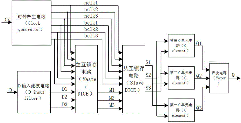
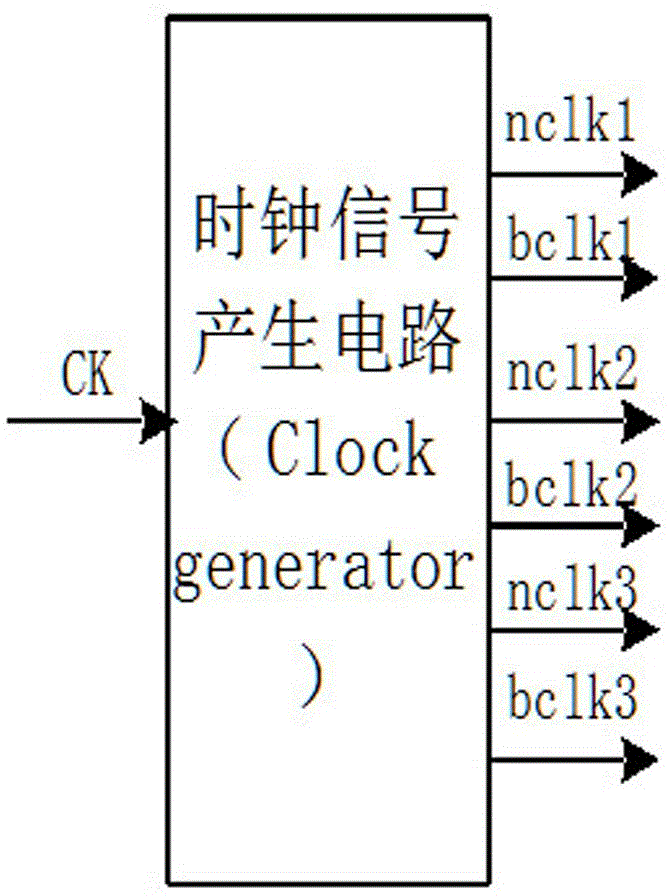
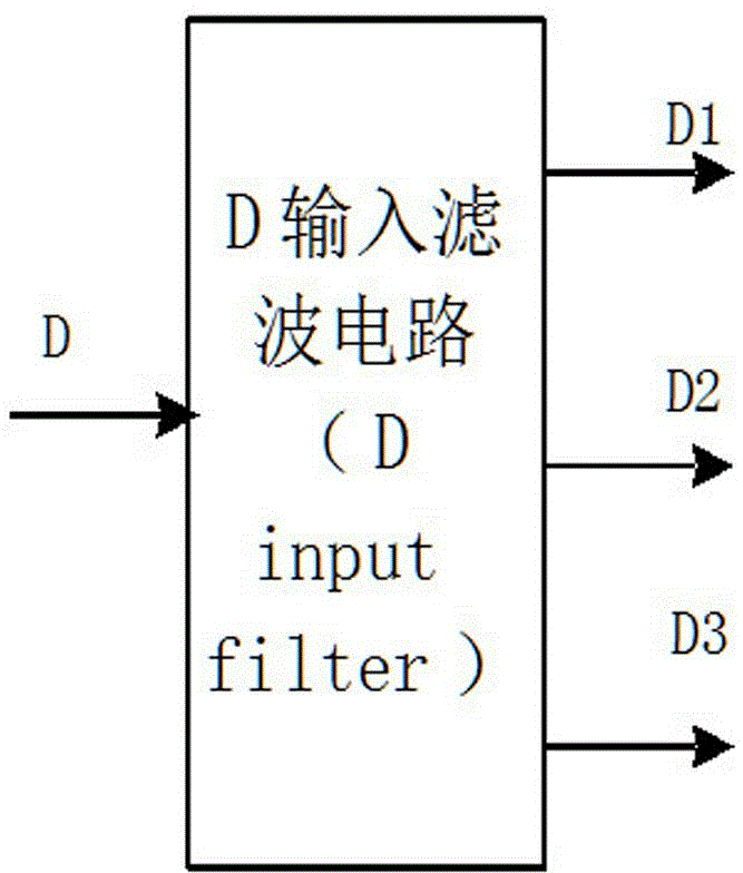
[0019] Depend on figure 1 , figure 2 , image 3 , Figure 4 , Figure 5 , Image 6 , Figure 7 , Figure 8 It can be seen that a radiation-resistant hardened flip-flop circuit based on a complex triple interlocked storage cell (DICE) in this embodiment is composed of a clock signal generation circuit (Clock generator), a D input filter circuit (D input filter) , C unit circuit (C element) and voting circuit (voter), master interlock circuit (Master DICE) and s...


PUM


Abstract

The invention discloses a radiation-resistant hardened trigger circuit based on a complex three-interacting latch unit; the radiation-resistant hardened trigger circuit is composed of a clock signal generation circuit, a D input filter circuit, a C unit circuit, a voting circuit, a main interlocking latch circuit and a slave interlocking latch circuit; the C unit circuit comprises a first C unit circuit, a second C unit circuit and a third C unit circuit; a clock signal, generated from an external clock signal CK through the clock signal generation circuit, and a data signal, generated from an external data signal D through the D input filter circuit, pass through the main interlocking latch circuit, the slave interlocking latch circuit and the C unit circuit; and then, an output signal Q of a whole trigger is output through the voting circuit. According to the technical scheme provided by the invention, by adopting a technology for hardening a trigger using a complex three-interacting latch circuit, output of the whole trigger circuit can be ensured to be steady when the trigger circuit is turned due to the fact that the trigger circuit is subjected to interferences, such as radiation; therefore, the reliability is increased; and the radiation-resistance capability of the trigger circuit is greatly increased.

Description

technical field [0001] The invention relates to the design of an anti-radiation circuit, in particular to an anti-radiation hardened trigger circuit based on a complex three-interlock unit. Background technique [0002] With the advancement of integrated circuit manufacturing technology, the reduction of device size and the improvement of operating speed, the influence of radiation on circuits has become more and more serious. The main impact of radiation on digital circuits is reflected in the single event effect and total dose effect. As deep submicron MOS devices become mainstream, especially when the process node of MOS circuits reaches below 65nm, the single event effect has become the most important factor affecting MOS devices. radiation effect. Single event effects are mainly divided into single event transients and single event upsets. [0003] In the radiation environment, MOS integrated circuits are bombarded by high-energy charged particles, especially the circ...

Claims


Application Information

Patent Timeline
IPC IPC(8): H03K3/02
Inventor 丁文祥夏冰冰吴军汪信华蔡雪原
Owner ANQING NORMAL UNIV
Why Eureka
Try Eureka