Micro-abrasive material water-jet cutting head apparatus

A technology of cutting head and material water, which is applied in the direction of abrasive feeding device, abrasive, grinding/polishing equipment, etc., can solve the problems of uncontrollable abrasive flow, uneven abrasive suction, and failure of abrasive conveying system, so as to prevent abrasive The effect of failure of the conveying system, controllable feeding flow rate and high feeding reliability

Inactive Publication Date: 2015-03-11
SHAANXI QIYUAN TECH DEV
View PDF0 Cites 10 Cited by
  • Summary
  • Abstract
  • Description
  • Claims
  • Application Information

AI Technical Summary

Problems solved by technology

However, if the traditional abrasive water jet cutting head and the negative pressure suction abrasive method are used, there are many problems
Because the microabrasive waterjet needs to use high-precision submicron or even nanoscale abrasive particles, because the fine particles can easily absorb moisture in the air, which increases the viscous resistance of the abrasive flow process, therefore, when the abrasive is sucked by negative pressure, the abrasive is in the air. Abrasive pot drop opening arches
Causes uneven abrasive suction, uncontrollable abrasive flow, high failure rate, directly affects cutting efficiency and processing quality
In severe cases, the spray head is blocked, and the high-pressure water will return to the abrasive tank through the feeding pipe to wet the abrasive. Causing the abrasive delivery system to fail

Method used


Image

  • Micro-abrasive material water-jet cutting head apparatus

Examples


Embodiment Construction

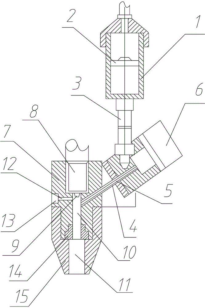
[0011] The microabrasive water jet cutting head device of the present invention includes a storage tank 1, a mixing chamber 10 and a spray head 7. A piston 2 is arranged in the storage tank 1, and the piston 2 divides the storage tank into a compressed air chamber and a slurry abrasive A feeding hose 3 is connected to the lower end of the storage tank 1, and the feeding hose 3 is connected to the mixing chamber 10 through the screw pump casing 4. A feeding screw 5 connected to the stepping motor 6 is arranged in the screw pump casing 4. The mixing chamber 10 is set in the spray head 7, the upper end of the spray head 7 is provided with a high-pressure water chamber 8, the lower end of the high-pressure water chamber 8 is connected to the mixing chamber 10 through the water nozzle 9, and the lower end of the mixing chamber 10 is provided with a mixture nozzle 11 . A drainage channel 12 is opened on the mixing chamber 10, and a one-way valve 13 is arranged on the drainage channe...


PUM


Abstract

The invention discloses a micro-abrasive material water-jet cutting head apparatus, and relates to the field of mechanical processing equipment, particularly to a micro-abrasive material water-jet cutting head apparatus, which comprises a material storage tank, a mixing chamber and a spraying head, wherein a piston is arranged in the material storage tank, the material storage tank is divided into a compressed air cavity and a slurry abrasive material cavity through the piston, the lower end of the material storage tank is connected with a material feeding soft pipe, the material feeding soft pipe is connected with the mixing chamber through a screw pump shell, a material feeding screw connected with a stepper motor is arranged in the screw pump shell, the mixing chamber is arranged in the spraying head, the upper end of the spraying head is provided with a high pressure water chamber, the lower end of the high pressure water chamber is connected with the mixing chamber through a water spraying nozzle, and the lower end of the mixing chamber is provided with a mixed material spraying pipe. According to the present invention, the screw is adopted to perform the active material feeding, such that the material feeding reliability is high, the suction is uniform, the material feeding flow can be controlled, and the abrasive material conveying system failure caused by directly entering of the high temperature water into the abrasive material tank after the clogging of the spraying head can be prevented.

Description

technical field [0001] The invention relates to the field of machining equipment, in particular to a microabrasive water jet cutting head device. Background technique [0002] Microabrasive water jet is a new, efficient, green and environmentally friendly form of high-energy beam. Micro-abrasive water jet processing uses water jet beams to accelerate abrasive particles, and uses its kinetic energy to etch away matrix materials. The processing of sensitive and pressure-sensitive materials, combined with the CNC system, it is easy to realize plane milling and three-dimensional engraving. Due to its small slit width, high etching precision, no thermal influence, and no choice of materials, it has been highly valued and researched in Europe, America and other countries in recent years, and can be used as a single production method for semiconductors, micro-electromechanical systems and optical devices. Low-cost, flexible high-energy beam processing method. [0003] Miller use...

Claims


Application Information

Patent Timeline
Patent Type & Authority Applications(China)
IPC IPC(8): B24C5/00B24C7/00
CPCB24C7/0092B24C5/00B24C7/0007
Inventor 张淑芬
Owner SHAANXI QIYUAN TECH DEV
Why Eureka
Try Eureka