
Internal inlet gas gas-cooling device of coagulation enhancing block of polycrystalline silicon ingot furnace and polycrystalline silicon ingot furnace

A technology of polycrystalline silicon ingot furnace and air cooling device, which is applied in the directions of polycrystalline material growth, single crystal growth, crystal growth, etc., can solve the problems of reduced ingot solidification speed, long contact time, diffusion pollution, etc., and achieves improved cooling crystallization. speed, improve heat dissipation, and reduce production costs

Inactive Publication Date: 2015-03-04
HARBIN INST OF TECH
View PDF8 Cites 5 Cited by
  • Summary
  • Abstract
  • Description
  • Claims
  • Application Information

AI Technical Summary

Problems solved by technology

However, since the size of the furnace body remains unchanged after the transformation, the weight of the ingot after the transformation increases by 44% and 96% respectively, and the heat dissipation capacity at the bottom of the thermal field needs to be improved accordingly. The heat dissipation capacity of the existing heat insulation cage lifting technology is only slightly improved, so the It will greatly reduce the solidification rate during the ingot casting process
For example, the solidification time of G5 ingot is about 25 hours, but the solidification time of G6 ingot is about 40 hours, and the solidification time of G7 ingot is longer
This virtually increases the cost of silicon wafer production, and at the same time, during the solidification process, most of the silicon material is still in a high-temperature melting state, which also increases the risk of silicon leakage
In addition, due to the long contact time between the silicon ingot and the crucible, it will also cause a certain diffusion pollution of oxygen, which will reduce the quality of the crystal.

Method used


Image

  • Internal inlet gas gas-cooling device of coagulation enhancing block of polycrystalline silicon ingot furnace and polycrystalline silicon ingot furnace
  • Internal inlet gas gas-cooling device of coagulation enhancing block of polycrystalline silicon ingot furnace and polycrystalline silicon ingot furnace
  • Internal inlet gas gas-cooling device of coagulation enhancing block of polycrystalline silicon ingot furnace and polycrystalline silicon ingot furnace

Examples


Embodiment 1

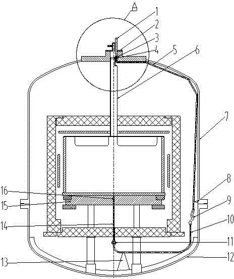
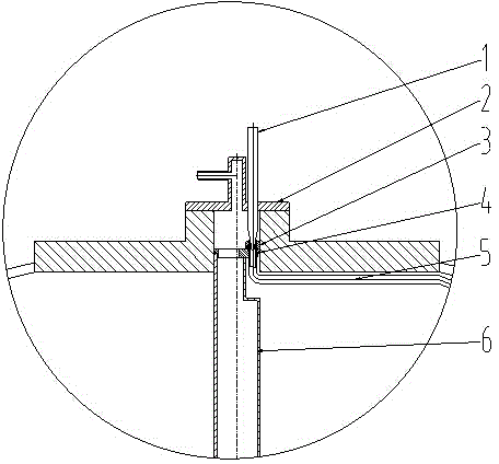
[0031] The present embodiment comprises roof cover 2, air inlet pipe cover 4, inner air inlet pipe I5, inner air inlet pipe II9, inner air inlet pipe III10, inner air inlet pipe IV14, clotting aid 15, and the inner air inlet pipe I5 inlet end passes through the air inlet pipe The small air intake hole 20 of lid 4; Inlet air intake pipe I5, interior air intake pipe II9, interior air intake pipe III10 and interior air intake pipe IV14 are connected successively, and interior air intake pipe IV14 stretches in the help clot 15 center hole 16 (as figure 1 shown).

[0032] In order to control the on-off cooling gas, a conical rod 1 is arranged on the furnace roof 2, and the conical end of the conical rod 1 can extend into the air inlet of the inner air inlet pipe I5, and the diameter of the conical rod 1 is larger than that of the inner air inlet. The inner diameter of the intake pipe I5. Because the diameter of tapered rod 1 is greater than the inner diameter of inner air inlet pi...

Embodiment 2

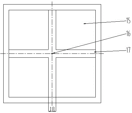
[0044] The difference between the present embodiment and embodiment 1 is only: the width 18 of the air guide groove 17 on the top of the clot 15 is 500mm, and the depth 19 is 0.5mm; the inner air intake pipe IV14 is a graphite tube; The diameter ratio of the hole 20 to the large air intake hole 21 is 0.8:1; the diameter of the large air intake hole 21 is 35 mm, and the diameter of the small air intake hole 20 is 28 mm; the cooling gas is an inert gas argon. The rest are the same as embodiment 1.

[0045] Taking GT ingot furnace G5 transformed into G6 as an example, the weight of the ingot is increased from 500 kg to 800 kg. If the crystal growth scheme of lifting the heat insulation cage is simply adopted, the crystal growth time will take about 40 hours, and the overall process The time is 75 hours; and after adopting the air inlet air cooling device in the polysilicon ingot furnace of the present invention to help clot, the crystal growth time is shortened to 30 hours, and t...

Embodiment 3

[0047] The difference between this embodiment and embodiment 1 is only: the nut 3 is a carbon-carbon composite material nut; the width 18 of the air guide groove 17 arranged on the top of the clot 15 is 250mm, and the depth 19 is 10mm; the inner air intake pipe IV14 is graphite Tube; the diameter ratio=0.6:1 of the small air intake hole 20 and the large air intake hole 21 of the intake pipe cover 4, the diameter of the large air intake hole 21 is 35mm, and the diameter of the small air intake hole 20 is 21mm; the cooling gas is inert Gas Argon.

[0048] Taking GT ingot furnace G5 transformed into G6 as an example, the weight of the ingot is increased from 500 kg to 800 kg. If the crystal growth scheme of lifting the heat insulation cage is simply adopted, the crystal growth time will take about 40 hours, and the overall process The time is 75 hours; and after adopting the air inlet air cooling device in the ingot casting furnace of the present invention to help the clot, the c...


PUM

PropertyMeasurementUnit
widthaaaaaaaaaa
depthaaaaaaaaaa

Abstract

The invention discloses an internal inlet gas gas-cooling device of a coagulation enhancing block of a polycrystalline silicon ingot furnace and a polycrystalline silicon ingot furnace, belonging to the technical field of photovoltaic solar polycrystalline silicon ingot furnaces. The internal inlet gas gas-cooling device comprises a furnace top lid (2), a gas inlet tube lid (4), an internal gas inlet tube I (5), an internal gas inlet tube II (9), an internal gas inlet tube III (10), an internal gas inlet tube IV (14) and a coagulation enhancing block (15), wherein the internal gas inlet tube I (5) passes through a small gas inlet (20) of the gas inlet tube lid (4); the internal gas inlet tube IV (14) extends to a central hole (16) of the coagulation enhancing block (15). By virtue of an unique structural design, the internal inlet gas gas-cooling device of the coagulation enhancing block of the polycrystalline silicon ingot furnace disclosed by the invention can be used for introducing cooling gas into the coagulation enhancing block (15) to cool the coagulation enhancing block (15), so that the heat dissipation capability of the coagulation enhancing block (15) is improved, and therefore, the cooling and crystallization rate of silica melt in a crucible can be increased, and the directional solidification efficiency is improved. Meanwhile, the silica melt is enabled to form considerable super-cooling degree, so that a proper silicon twin crystal structure is produced, and the ingot quality is improved.

Description

technical field [0001] The invention relates to a polysilicon ingot furnace, in particular to a polysilicon ingot furnace air-cooling device for the air intake inside the coagulation-assisting block, and a polysilicon ingot furnace including the air-cooling device for the air intake inside the clot-assisting block. technical background [0002] The growth of silicon crystals is generally divided into three methods: polycrystalline ingot, single crystal pulling and zone melting growth. With the large-scale application of crystalline silicon photovoltaic products, the solar-grade crystalline silicon wafer industry continues to develop and mature. The price of raw materials has gradually dropped, causing the profit margins of silicon wafer manufacturers to continue to shrink. Improving the quality of silicon wafers and reducing processing costs have become issues facing all solar silicon wafer manufacturers. The industrial chain of crystalline silicon photovoltaic power genera...

Claims


Application Information

Patent Timeline
Patent Type & Authority Applications(China)
IPC IPC(8): C30B29/06C30B28/06
CPCC30B29/06C30B28/06
Inventor 吕铁铮
Owner HARBIN INST OF TECH
Learn More