A wire-drawing processing device for the surface of an asymmetric cylindrical curved surface mold core of an injection mold

A technology for injection molding and wire drawing processing, which is applied in the direction of fixed grinding wheel devices, metal processing equipment, manufacturing tools, etc. It can solve the problems of difficult grinding, consuming a lot of time and manpower, poor corrosion treatment, etc., and achieve the effect of reducing processing time

Inactive Publication Date: 2018-01-09
TIANJIN FANJIN MOLD
View PDF6 Cites 0 Cited by
  • Summary
  • Abstract
  • Description
  • Claims
  • Application Information

AI Technical Summary

Problems solved by technology

There are many drawing surface processing methods such as grinding of cavity or core of the mold, corrosion processing, laser processing, buffing processing, etc. Usually, the grinding of the core is only suitable for plane processing, and the core of the asymmetric cylindrical surface shape , It is difficult to grind, so it is mainly used for corrosion processing, such as this kind of asymmetrical cylindrical mold core, it takes a lot of time and manpower to process corrosion, and frequent bad problems occur when the corrosion treatment is not smooth

Method used


Image

  • A wire-drawing processing device for the surface of an asymmetric cylindrical curved surface mold core of an injection mold
  • A wire-drawing processing device for the surface of an asymmetric cylindrical curved surface mold core of an injection mold
  • A wire-drawing processing device for the surface of an asymmetric cylindrical curved surface mold core of an injection mold

Examples


Embodiment Construction

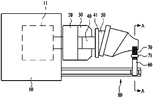
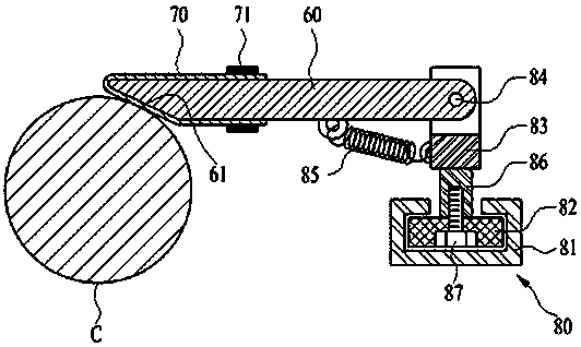
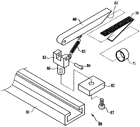
[0018] see Figure 1 to Figure 4 , this specific embodiment adopts the following technical solutions: it includes a body 10 with a driver, a rotating body 20 connected to the body 10, a fixed disk 30 mounted on the rotating body 20, a rotating shaft 40 engaged with the fixed disk 30, and a rotating The inclined block 50 combined with the shaft 40 , the holder 60 corresponding to the mold core C, the sandpaper 70 fixed at the end of the holder 60 , and the elastic support part 80 arranged between the body 10 and the holder 60 .

[0019] Wherein, the main body 10 is provided with a driver 11, and the driver 11 drives the rotating body 20, thereby driving the mold core C. The fixed disk 30 is arranged at the end of the rotating body 20 , and functions to fix the rotating shaft 40 and also loosen the rotating shaft 40 . The rotating shaft 40 is fixed on the fixed disk 30 , and the end of the rotating shaft 40 is provided with a disk 41 to facilitate the installation of the tiltin...


PUM


Abstract

The invention relates to the technical field of mould machining, in particular to a wire drawing machining device for the surface of an asymmetric and cylindrical curved surface mould core of an injection mould. The wire drawing machining device comprises a body with a driver, a rotating body connected with the body, a fixed disc installed on the rotating body, a rotation shaft meshed with the fixed disc, an inclined block combined with the rotation shaft, a fixator corresponding to the mould core, abrasive paper fixed to one end of the fixator, and an elastic supporting portion arranged between the body and the fixator. The wire drawing machining device enables the asymmetric and cylindrical curved surface mould core to be machined in a buffing mode, thereby obviously shortening the machining time of a surface subjecting to wire drawing, saving manpower and reducing the machining reject ratio.

Description

Technical field: [0001] The invention relates to the technical field of mold processing, in particular to a wire drawing processing device for the surface of an asymmetric cylindrical curved mold core of an injection mold. Background technique: [0002] In general, the hair line is the final surface treatment method of IT products or high-end home appliances. It is a method of repeatedly superimposing multiple very thin lines. Scribing work on thin metal plates such as aluminum or stainless steel plates). [0003] .Recently, in the appearance of injection molding products, the brushed surface is also processed to replace the metal plate. Its texture is very similar to the processing effect of the metal plate. After the drawing surface is processed on the cavity or core, it is injection molded into a product to reflect the method of drawing the surface. There are many drawing surface processing methods such as grinding of cavity or core of the mold, corrosion processing, la...

Claims


Application Information

Patent Timeline
Patent Type & Authority Patents(China)
IPC IPC(8): B24B19/20B24B41/04B24B45/00
CPCB24B19/20B24B41/04B24B45/00
Inventor 朴正吉朴虎聲
Owner TIANJIN FANJIN MOLD
Why Eureka
Try Eureka