Compression-joint type IGBT packaging structure with heat tubes

A packaging structure, crimping technology, applied in electrical components, electrical solid devices, circuits, etc., can solve the problems of mechanical damage to the chip, poor thermal conductivity on the side of the chip, and inability to balance chip protection and thermal conductivity, and achieve overall thermal resistance. Small, small chip protection effect

Inactive Publication Date: 2015-01-14
STATE GRID CORP OF CHINA +1
View PDF7 Cites 12 Cited by
  • Summary
  • Abstract
  • Description
  • Claims
  • Application Information

AI Technical Summary

Problems solved by technology

[0005] The invention patent with the publication number CN1596472A discloses a high-power semiconductor module. In its structure, the lower side of the chip is sintered with the substrate, and the other side is a crimping structure, and finally contacts the upper end cover through the disc spring structure. The disc spring structure The use of the device makes the device have the advantage of protecting the chip, that is, when the pressing force is too large, the excess pressure will be borne by the shell of the device, and the force on the chip is only related to the compressible length of the disc spring, but also because of the existence of the disc spring , so that the thermal conductivity of the upper side of the chip is very poor, the heat can only be exported through the lower side, and the overall thermal resistance is relatively large
[0006] In the structure of the patent with the publication number US6678163B1, the upper and lower sides of the chip are all crimped structures, up to the upper and lower end caps. The advantage of this structure is that the device can realize double-sided heat dissipation, and the upper and lower sides of the chip have almost equal heat output. The overall thermal resistance is small, but because of the hard crimping structure in the vertical direction, the chip bears all the pressing force when the device is pressed, and the force on the chip also increases when the pressing force is too large, so The chip may be mechanically destroyed by excessive pressure
[0007] Through the above analysis, it can be seen that the products of the two companies have their own advantages, but they also have their own shortcomings. Chip protection and heat conduction cannot be balanced.

Method used


Image

  • Compression-joint type IGBT packaging structure with heat tubes
  • Compression-joint type IGBT packaging structure with heat tubes
  • Compression-joint type IGBT packaging structure with heat tubes

Examples


Embodiment 1

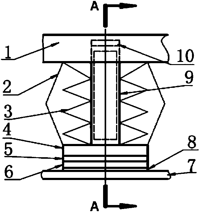
[0051] There are multiple subunits inside the device, and one subunit is a stacked structure as a whole, and there are one or more chips 8 inside it. The periphery of the subunit is protected by the tube shell. In the non-working state, the upper end surface of the subunit is slightly higher than the upper end surface of the tube shell, and the typical value is 2-3mm.

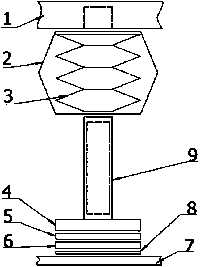
[0052] like Figure 1~5 As shown, the IGBT package structure from bottom to top is the lower end cover 7, chip 8, upper molybdenum sheet 6, silver sheet 5 (or aluminum sheet), base 4, conductive copper sheet 2 (lower end), heat pipe, disc spring group 3, Conductive copper sheet 2 (upper end), upper end cover 1.

[0053]Among them, the chip 8 can be directly crimped with the lower end cover 7, and can also be sintered with the lower end cover 7. In addition, the upper end cover 1 has a deep hole at the position corresponding to the heat pipe, and the upper end of the heat pipe is inserted into it. It is ensure...

Embodiment 2

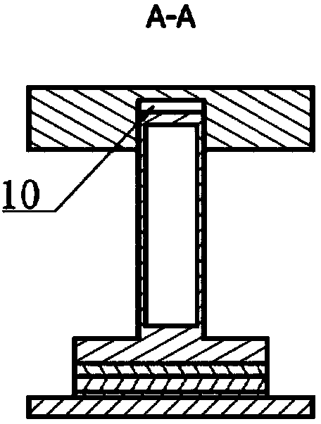
[0056] like Figure 6 and Figure 7 As shown, the lower structure is the same as that of Embodiment 1, except that a through hole is opened at the corresponding position of the upper end cover 1 and the heat pipe, and the heat pipe passes through it, and then a hole with a certain depth is opened at the corresponding position on the radiator, which is filled with high-efficiency thermal grease 10. It can ensure that there is a better heat conduction path between the heat pipe passing through the heat conduction grease 10 and the heat sink in the working state.

Embodiment 3

[0058] like Figure 8 and Figure 9 As shown, there are several grooves at the bottom of the base 4, in which the heat pipe can be embedded, and at the same time be compressed between the base 4 and the upper molybdenum sheet 6, so as to ensure that the heat can be better transferred from the molybdenum sheet 6 to the heat pipe, and then the heat pipe from Both sides of the base 4 are bent upward until reaching the corresponding deep holes of the upper end cover 1 , and the same deep holes are filled with high-efficiency thermal conductive grease 10 . In the figure, there are heat pipes on both sides of the base 4, or only on one side. Also similar to Embodiment 2, the upper end cover 1 may also have a through hole through which the heat pipe passes to a deep hole at a corresponding position on the radiator, and the deep hole is filled with high-efficiency thermal grease 10 . In addition, the guide rod of the base 4 can also be a heat pipe as in the first two embodiments.

...


PUM

PropertyMeasurementUnit
Thicknessaaaaaaaaaa
Thicknessaaaaaaaaaa
Thicknessaaaaaaaaaa

Abstract

The invention provides a compression-joint type IGBT packaging structure with heat tubes. The compression-joint type IGBT packaging structure is composed of an outer shell and a plurality of sub-unit structures located inside the outer shell, and the multiple sub-unit structures are arranged in parallel. Each sub-unit structure comprises an upper end cover, conductive copper sheets, a disc spring set, the heat tube, a base, a silver sheet, a molybdenum sheet, a chip and a lower end cover, wherein the lower end cover, the chip, the molybdenum sheet, the silver sheet and the base are sequentially arranged from bottom to top, the upper end of the heat tube is inserted into the upper end cover and penetrates through the disc spring set, the lower end of the heat tube is inserted into the base, the upper ends of the conductive copper sheets are located between the upper end cover and the disc spring set, and the lower ends of the conductive copper sheets are located between the disc spring set and the base. By means of the compression-joint type IGBT packaging structure, the chips can be effectively protected; meanwhile, as the heat tubes are used, two-sided radiating is achieved in function, and the overall heat resistance is small; as the heat tubes are introduced, although single-face hard contact is generated, a radiating path is good, and consideration is given to chip protection and the small heat resistance. The overall structure has the advantages that short circuit efficacy losing of a compression-joint type IGBT is achieved, and reliability is high.

Description

technical field [0001] The invention relates to a packaging structure, in particular to a crimping type IGBT packaging structure using a heat pipe. Background technique [0002] Insulated gate bipolar transistor (IGBT) has the characteristics of on-state voltage drop, large current capacity, high input impedance, fast response and simple control, and is widely used in industry, information, new energy, medicine, transportation, military and aviation fields . The crimp IGBT has high reliability, is easy to be connected in series, and exhibits a short-circuit failure mode when the device is damaged, so it is widely used in fields such as smart grids. [0003] The influence of temperature on device performance is very important. High temperature will not only affect the electrical characteristics of the device, but also seriously affect its fatigue life. During the operation of the device, the temperature will affect the thermal stress inside the chip, which may lead to damag...

Claims


Application Information

Patent Timeline
IPC IPC(8): H01L23/31H01L23/427
CPCH01L23/31H01L23/427H01L2924/0002H01L2924/00
Inventor 刘文广韩荣刚张朋
Owner STATE GRID CORP OF CHINA
Why Eureka
Try Eureka