
Insulating rod for 500kV equipment high-voltage test working

A high-voltage test and insulating rod technology, which is applied to the parts, measuring devices, instruments and other directions of electrical measuring instruments, can solve the problems that the insulating rod cannot be hung firmly, the test line cannot be suspended, and the suspension of the insulating rod is difficult. The effect of testing data accuracy, enhancing work safety, and reducing the risk of slipping

Inactive Publication Date: 2015-01-14
MAINTENANCE BRANCH STATE GRID LIAONING ELECTRIC POWER +1
View PDF1 Cites 0 Cited by
  • Summary
  • Abstract
  • Description
  • Claims
  • Application Information

AI Technical Summary

Problems solved by technology

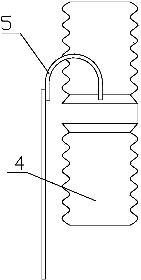
While working, the testers found that when some equipment such as 500kV voltage transformers were suspended by insulating rods for test connection, the insulating rods could not be hung firmly on the ground due to the mismatch between the shape of the tested equipment and the shape of the insulating rod head. On the equipment, it is difficult to hang the insulating rod during work, and the suspension is not stable or even slipped down, which is easy to injure the operator and cause a safety accident. See figure 1
[0003] The existing patent application number is 201120272824.6 patent: 10kV insulating operating rod. This patent discloses a structure with a "C"-shaped operating head, but this structure is a fuse tube suitable for fuses. The "C"-shaped operating head and the insulating A horizontal column 2b and a vertical column 2a are added to the connection of the rod body. The horizontal column 2b and the operating head are made of elastic materials, which belong to the scope of professional use for maintenance, and are not insulating rods for high-voltage tests. This structure cannot realize the suspension of test lines.

Method used


Image

  • Insulating rod for 500kV equipment high-voltage test working
  • Insulating rod for 500kV equipment high-voltage test working
  • Insulating rod for 500kV equipment high-voltage test working

Examples


Embodiment Construction

[0014] The present invention will be described in detail below in conjunction with the accompanying drawings, but it should be pointed out that the implementation of the present invention is not limited to the following embodiments.

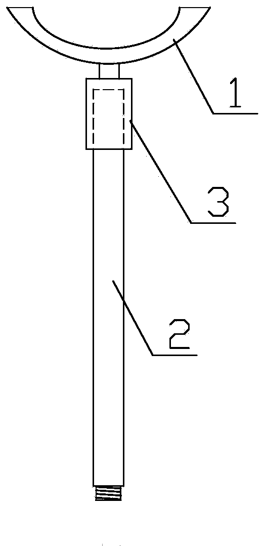
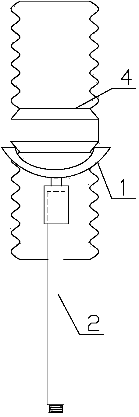
[0015] See figure 2 , image 3 , the insulating rod used for the high-voltage test operation of 500kV equipment, including the insulating rod head 1 and the insulating rod body 2, the insulating rod head 1 is an arc-shaped structure, and is connected with the insulating rod body 2 in the middle of the arc-shaped structure. Among them, a threaded sleeve 3 is welded in the middle of the insulating rod head 1, and the insulating rod body 2 and the insulating rod head 1 are connected through the threaded sleeve 3; the arc-shaped structure matches the equipment under test.

[0016] According to the size of the upper section of the existing insulating rod body 2, a threaded sleeve 3 that can match the insulating rod body 2 is manufactured, and an ins...


PUM


Abstract

The invention relates to an insulating rod for 500kV equipment high-voltage test working. The insulating rod comprises an insulating rod head and an insulating rod body. The insulating rod head is of a circular arc structure. The middle of the circular arc structure is connected with the insulating rod body. The insulating rod further comprises a thread bushing. The thread bushing is fixedly connected to the middle of the insulating rod head. The insulating rod body is connected with the insulating rod head through the thread bushing. The insulating rod has the advantages that multi-point contact between the insulating rod and tall and big equipment can be achieved by the adoption of the insulating rod head of the circular arc structure, and the contact area between the rod head and the tested equipment is increased. The insulating rod is convenient to carry, and wires can be hung easily and firmly. Due to the connecting mode of the thread bushing, the insulating rod body and the insulating rod head can be disassembled at will, and the working reliability is high.

Description

technical field [0001] The invention relates to an insulating rod used for high-voltage test operation of 500kV equipment, which is used for hanging test connection lines of the insulating rod. Background technique [0002] In the 500kV on-site high-voltage test work, the insulating rod plays the role of ensuring a safe distance and realizing the suspension of the test line for tall equipment, ensuring the accuracy of the test data. While working, the testers found that when some equipment such as 500kV voltage transformers were suspended by insulating rods for test connection, the insulating rods could not be hung firmly on the ground due to the mismatch between the shape of the tested equipment and the shape of the insulating rod head. On the equipment, it is difficult to hang the insulating rod during work, it is not stable after hanging or even slips down, which is easy to hurt the operator and cause a safety accident. See figure 1 . [0003] The existing patent applic...

Claims


Application Information

Patent Timeline
IPC IPC(8): G01R1/02
Inventor 杨越张晓娜安全何娇王皓姜修平伏忠旺闻翰刘诗琪王澜唐俭王钢张哲李玉峰何鑫姜兴业张丽娟
Owner MAINTENANCE BRANCH STATE GRID LIAONING ELECTRIC POWER
Learn More