
Minimum leak rate calibrating method based on static ion flow rising rate comparison method

A static ion flow, extremely small leak rate technology, applied in the direction of detecting the appearance of fluid at the leak point, using liquid/vacuum for liquid tightness measurement, etc., can solve the problem of the extremely small leak rate signal being submerged by the background, etc. , to achieve the effect of enhancing signal strength, increasing concentration, improving stability and reliability

Inactive Publication Date: 2015-01-14
LANZHOU INST OF PHYSICS CHINESE ACADEMY OF SPACE TECH
View PDF12 Cites 5 Cited by
  • Summary
  • Abstract
  • Description
  • Claims
  • Application Information

AI Technical Summary

Problems solved by technology

[0008] In view of this, the present invention provides a very small leak rate calibration method using the static ion current rising rate comparison method. The method adopts a static calibration method, which can effectively solve the problem that the very small leak rate signal is submerged by the background in the dynamic calibration method. problem, achieved 10 -10 Pa·m 3 Comparative calibration of the same level of extremely small leak rate below / s, which further extends the lower limit of calibration of the leak rate

Method used


Image

  • Minimum leak rate calibrating method based on static ion flow rising rate comparison method
  • Minimum leak rate calibrating method based on static ion flow rising rate comparison method
  • Minimum leak rate calibrating method based on static ion flow rising rate comparison method

Examples


Embodiment Construction

[0025] The present invention will be described in detail below with reference to the accompanying drawings and embodiments.

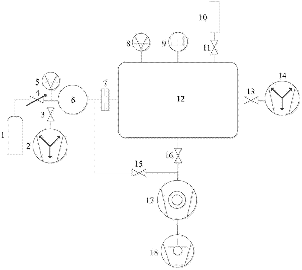
[0026] The present invention provides a method for calibrating a very small leak rate using a static ion current rising rate comparison method. figure 1The detection device shown is calibrated, and the detection device includes a gas cylinder 1, a non-evaporative getter pump a 2, a non-evaporative getter pump b 14, a stop valve a 3, a stop valve b 11, a stop valve c 13. Globe valve d 15, globe valve e 16, trim valve 4, vacuum gauge a 5, vacuum gauge b 8, pressure chamber 6, small hole piece 7, quadrupole mass spectrometer 9, minimum leak rate calibrated piece 10 , calibration chamber 12 , molecular pump 17 and dry pump 18 . Wherein, the series pumping system composed of the molecular pump 17 and the dry pump 18 is connected to the lower part of the calibration chamber 12 through the cut-off valve e 16, for pumping the calibration chamber 12 to ultra-hi...


PUM


Abstract

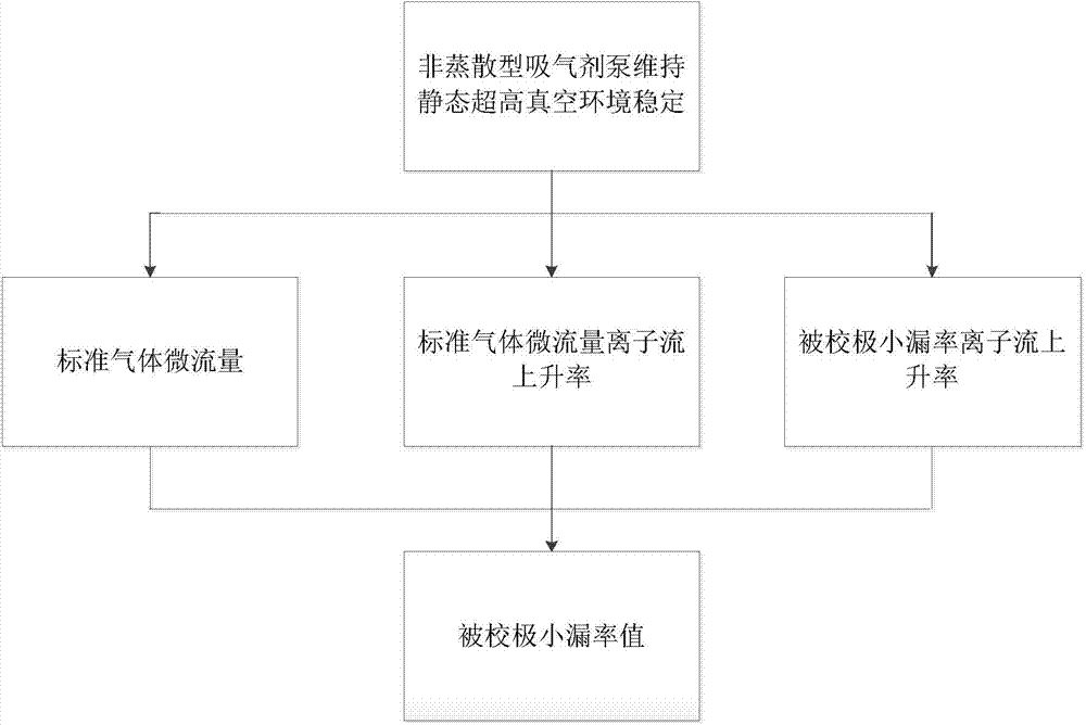
The invention discloses a minimum leak rate calibrating method based on the static ion flow rising rate comparison method. By the adoption of the minimum leak rate calibrating method based on the static ion flow rising rate comparison method, the problem that according to a dynamic calibrating method, a minimum leak rate signal is submersed by a background can be effectively solved, same-order comparison and calibration of minimum leak rates smaller than 10-10 Pa.m <3> / s are achieved, and the lower limit of calibration of the leak rate is further extended. According to the minimum leak rate calibrating method based on the static ion flow rising rate comparison method, a non-evaporating dispersion type getter pump is additionally arranged in a calibration chamber, active gas such as the H2, the CO and the CO[2] can be sucked at a high speed through the non-evaporating dispersion type getter pump, inert gas such as the He and the Ar is not sucked, in this way, all gas, flowing into the calibration chamber, of a calibrated piece with the minimum leak rate is reserved, the concentration of leak indication gas in the calibration chamber is increased, the intensity of an ion flow generated by the leak indication gas is increased, and then minimum leak rate comparison and calibration are achieved by measuring the leak rate of the calibrated piece with the minimum leak rate and the rising rate of the static state ion flow generated by micro standard gas flow.

Description

technical field [0001] The invention relates to the technical field of vacuum metering, in particular to a minimal leak rate calibration method using a static ion current rising rate comparison method. Background technique [0002] In the document "Calibration apparatus of vacuum leak by using constant conductance method. Mapan, 2007, 22(1): 39-44", a leak rate calibration method using the constant conductance method is introduced. This method utilizes the characteristic that the conductance value C of the small hole is constant under the condition of molecular flow. First, a known standard gas microflow Q is generated in the calibration chamber. s , as in formula (1); the standard gas microflow Q to flow into the calibration chamber s After stabilization, the corresponding dynamic standard ion current signal I was measured by the mass spectrometer s , and calculate the sensitivity of the quadrupole mass spectrometer; then let the calibrated leak rate (unknown leak rate ge...

Claims


Application Information

Patent Timeline
Patent Type & Authority Applications(China)
IPC IPC(8): G01M3/20
Inventor 李得天杨长青冯焱张伟文成永军习振华孙雯君
Owner LANZHOU INST OF PHYSICS CHINESE ACADEMY OF SPACE TECH
Learn More