
Microwave vacuum air pressure sintering furnace

A technology of air pressure sintering and microwave vacuum, which is applied in furnaces, muffle furnaces, cooking furnaces, etc., can solve the problems of low reaction temperature of microwave air pressure equipment, inability to apply pressure by microwave sintering equipment, and long production cycle, etc., to achieve high density, Good uniformity and fast sintering speed

Active Publication Date: 2015-01-14
湖南华冶微波科技有限公司
View PDF13 Cites 36 Cited by
  • Summary
  • Abstract
  • Description
  • Claims
  • Application Information

AI Technical Summary

Problems solved by technology

[0003] The purpose of the present invention is to provide a microwave vacuum pressure sintering device with fast switching between vacuum and high pressure, high temperature resistance and uniform temperature field, so as to solve the problem of long production cycle and uneven sintering of existing conventional sintering equipment, and low reaction temperature of microwave pressure equipment , The technical problem that the microwave sintering equipment cannot exert pressure

Method used


Image

  • Microwave vacuum air pressure sintering furnace
  • Microwave vacuum air pressure sintering furnace
  • Microwave vacuum air pressure sintering furnace

Examples


Embodiment Construction

[0027] The embodiments of the present invention will be described in detail below with reference to the accompanying drawings, but the present invention can be implemented in various ways defined and covered.

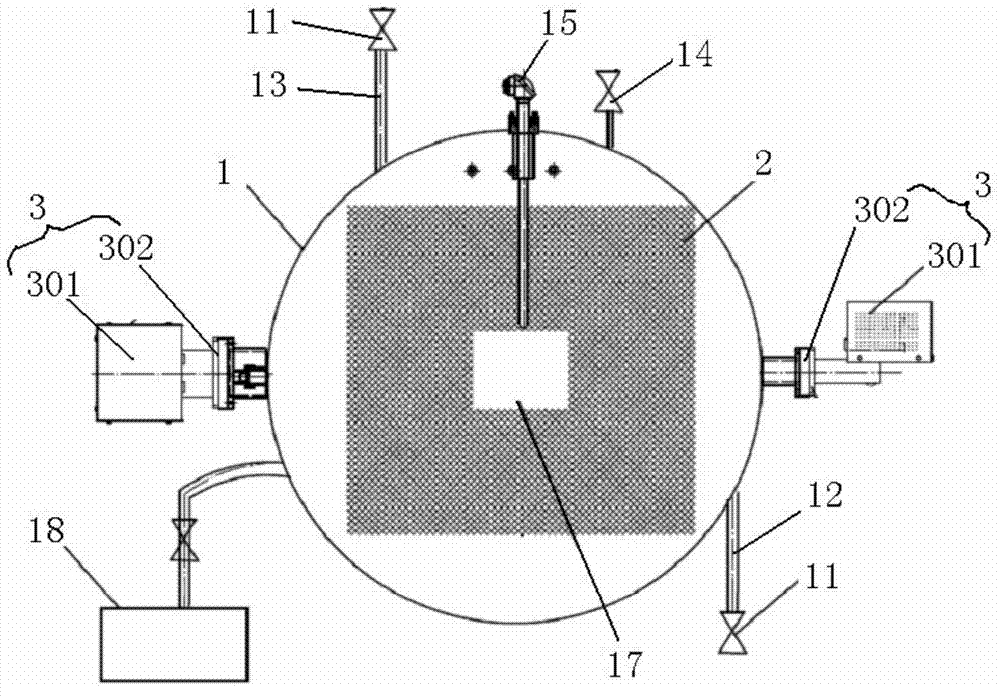
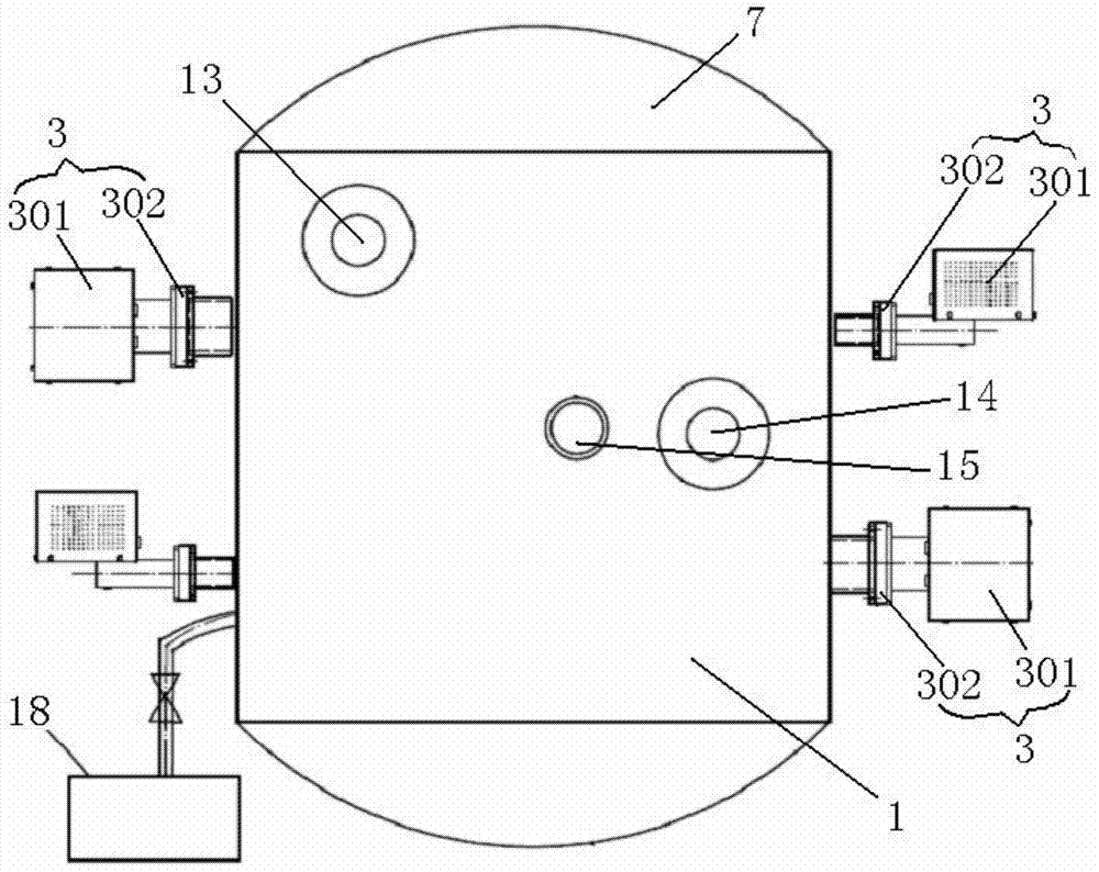
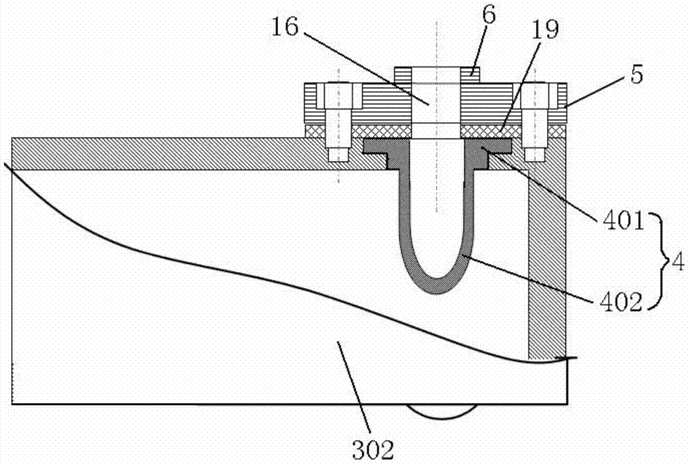
[0028] figure 1 It is one of the structural schematic diagrams of the microwave vacuum pressure sintering furnace in the preferred embodiment of the present invention; figure 2 It is the second structural diagram of the microwave vacuum pressure sintering furnace in the preferred embodiment of the present invention; image 3 is a schematic structural diagram of a microwave generating device in a preferred embodiment of the present invention; Figure 4 is a schematic structural diagram of a U-shaped flange in a preferred embodiment of the present invention; Figure 5 It is the third schematic diagram of the structure of the microwave vacuum pressure sintering furnace in the preferred embodiment of the present invention; Image 6 It is a structural schematic diagram o...


PUM

PropertyMeasurementUnit
Refractorinessaaaaaaaaaa

Abstract

The invention discloses a microwave vacuum air pressure sintering furnace, which comprises a furnace body, wherein the furnace body is connected with a vacuum pumping device and a pressurizing device, a heat insulation box body used for material sintering and heat loss reduction is arranged in the furnace body, the furnace body is provided with a micro wave generator used for feeding microwaves into an inner cavity of the furnace body, the microwave generator comprises a microwave source used for giving out the microwaves and a wave guide used for feeding the microwaves generated by the microwave source into the furnace body, the number of the microwave generator is one, a waveguide feed opening is formed in a direction towards the center of the heat insulation box body arranged in the furnace body, or the number of the microwave generators is several, the engaging directions of the microwave sources and the waveguide are in mutually vertical arrangement in the two adjacent microwave generators, in addition, the feeding-in direction of the waveguide engaged with the corresponding microwave sources deviates from the center of the heat insulation box, and the deviation distance of the feeding-in direction from the center of the heat insulation box is the odd number times of the wavelength of the microwaves. The uniform and fast sintering of high-density components adopting complicated structures can be realized.

Description

technical field [0001] The invention relates to the field of material sintering equipment, in particular to a microwave vacuum pressure sintering furnace. Background technique [0002] The sintering furnace is a furnace that densifies powder materials under the action of high temperature. It is mainly used in the sintering of structural ceramics, hard alloys, powder metallurgy and other materials. In the sintering process of these materials, it is first necessary to perform low-temperature degreasing and high-temperature sintering to increase the density of the material. Now the main heating methods of equipment are resistance heating and induction heating. Since the heating method is transferred to the material through heat convection and radiation, there are often many problems such as long production cycle, high energy consumption, uneven sintering, and poor product consistency. At present, none of the microwave sintering equipment can meet the requirements of high temp...

Claims


Application Information

Patent Timeline
IPC IPC(8): F27B5/05F27B5/14F27B5/18F27B5/06
Inventor 李德华潘慧娟向伯荣李斌
Owner 湖南华冶微波科技有限公司
Learn More