
Ring oscillator

A ring oscillator and main loop technology, applied in the direction of electrical components, automatic power control, etc., can solve the problem of ring oscillator jitter performance is not good enough, to achieve the effect of improving jitter performance, reducing delay, and increasing oscillation frequency

Active Publication Date: 2015-01-07
GUILIN UNIV OF ELECTRONIC TECH
View PDF5 Cites 11 Cited by
  • Summary
  • Abstract
  • Description
  • Claims
  • Application Information

AI Technical Summary

Problems solved by technology

[0005] The invention aims to solve the problem that the jitter performance of the existing ring oscillator is not good enough, and provides a ring oscillator, that is, a multi-feedback double-tuned injection-locked ring oscillator

Method used

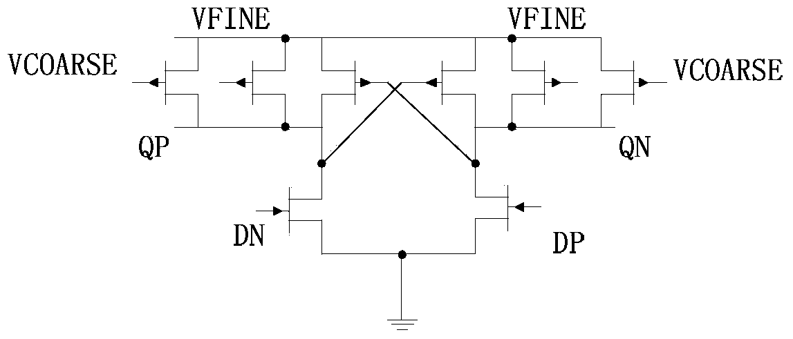
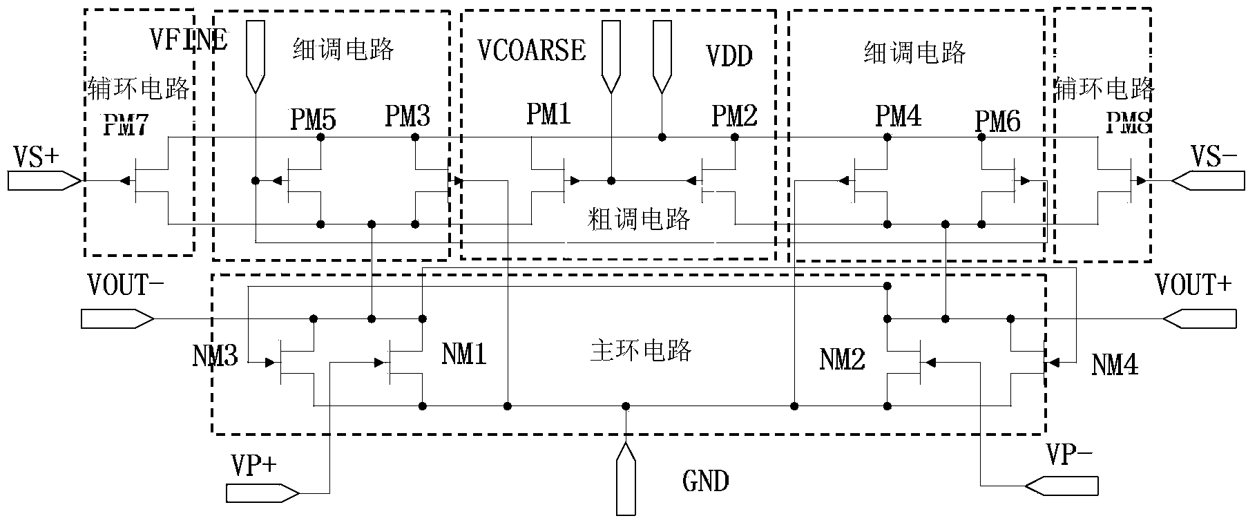

Image

  • Ring oscillator
  • Ring oscillator
  • Ring oscillator

Examples


Embodiment Construction

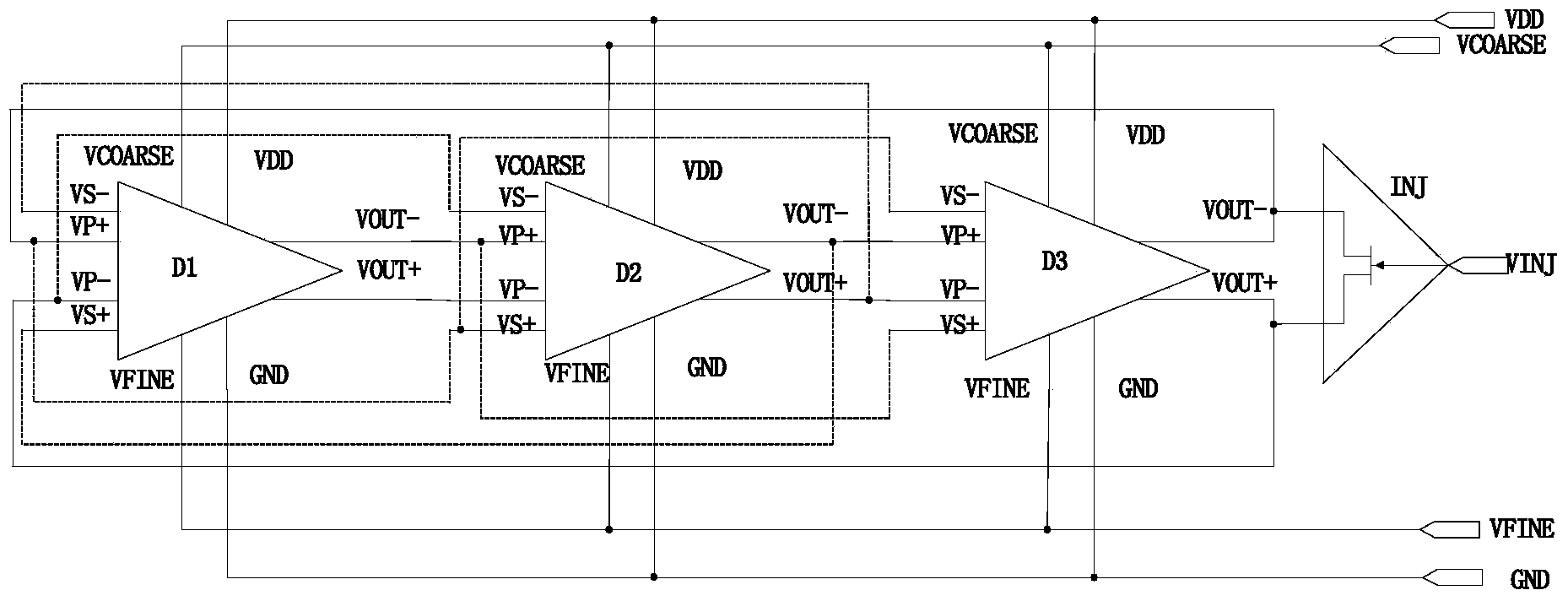
[0016] A ring oscillator such as figure 2As shown, it mainly consists of three differential delay units D1-D3 and one injection unit INJ. The differential non-inverting output terminal VOUT+ of the first differential delay unit D1 is connected to the main loop inverting input terminal VP- of the second differential delay unit D2, and the differential non-inverting output terminal VOUT+ of the second differential delay unit D2 is connected to the third differential delay unit D3 The main loop inverting input terminal VP-, the differential non-inverting output terminal VOUT+ of the third differential delay unit D3 is connected to the main loop inverting input terminal VP- of the first differential delay unit D1. The differential inverting output terminal VOUT- of the first differential delay unit D1 is connected to the main loop non-inverting input terminal VP+ of the second differential delay unit D2, and the differential inverting output terminal VOUT- of the second different...


PUM


Abstract

The invention discloses a ring oscillator. The ring oscillator mainly comprises three differential delay units D1, D2 and D3 connected in series and an injection unit INJ. 180-degree phase shift is realized from the input end of the first delay unit to the output end of the third serial-connection delay unit, the delay time is reduced through feedback of multiple loops, and the oscillation frequency is further improved. Each differential delay unit is provided with a rough tuning circuit and a fine tuning circuit, wherein the rough tuning circuit is used for setting the minimum delay or the maximum delay, and the fine tuning unit is used for adjusting the minimum delay and the maximum delay. Subharmonic signals at the frequency of output signals are injected to a grid electrode of the injection unit, and the shaking performance of the oscillator is improved. The ring oscillator has the rough tuning and fine tuning functions within the wide-frequency range, is low in voltage sensitivity, reduces the influences of bias voltage fluctuation, realizes low-shaking output clock signals and can be applied to a wireless receiver frequency synthesizer or a clock data recovery circuit.

Description

technical field [0001] The invention belongs to the field of integrated circuit design, and in particular relates to a ring oscillator. Background technique [0002] In recent years, electronic products are required to be able to meet the requirements of handheld multi-terminal communication, and almost all communication systems require a stable periodic signal, namely a clock, to provide the basic timing basis. These clock signals are typically generated by frequency synthesis techniques. The core of frequency synthesis technology is oscillator circuit design. There are generally two types of oscillator circuit structures: ring oscillators and LC oscillators. Because the circuit structure of the ring oscillator is simple, the process requirements are not high, and it is easy to integrate, so it has been widely used in the system on chip. [0003] The ring oscillator is composed of several basic differential delay unit circuits connected to form a loop, which is divided i...

Claims


Application Information

Patent Timeline
Patent Type & Authority Applications(China)
IPC IPC(8): H03L7/099
Inventor 徐卫林吴迪韦雪明段吉海韦保林
Owner GUILIN UNIV OF ELECTRONIC TECH
Learn More