Automatic front hydraulic guiding device for big stick hydraulic shear

An automatic guiding and hydraulic shearing technology, applied in guiding/positioning/aligning devices, shearing devices, attachment devices of shearing machines, etc. and other problems, to achieve the effect of convenient disassembly, assembly, maintenance and replacement, reducing production costs and energy consumption, and speeding up the rhythm of rolling.

Active Publication Date: 2015-01-07
JIANGSU LIANFENG ENERGY EQUIP
View PDF6 Cites 0 Cited by
  • Summary
  • Abstract
  • Description
  • Claims
  • Application Information

AI Technical Summary

Problems solved by technology

[0003] After the initial rolling of the large bar is completed by the blanking machine, in order to prevent the irregular billets from entering the continuous rolling directly to affect the quality of the product or damage the guides between the racks, hydraulic shears are usually used to cut the head and tail. , but the guide device in front of the existing hydraulic shear is a manual adjustment structure, which cannot move flexibly with the shearing movement of the hydraulic shear, and then causes the head and tail of the sheared billet to bend due to interference with the fixed guide device, making it difficult to enter Continuous rolling mill for subsequent rolling
Because the bending of the billet, especially at the head, will seriously affect the bite of the continuous rolling mill, which will not only affect the production rhythm of the rolling line, but also increase the production cost, and may also damage the rolling mill's roller table baffle, roller table guard, Guides and other auxiliary equipment

Method used


Image

  • Automatic front hydraulic guiding device for big stick hydraulic shear
  • Automatic front hydraulic guiding device for big stick hydraulic shear
  • Automatic front hydraulic guiding device for big stick hydraulic shear

Examples


Embodiment 1

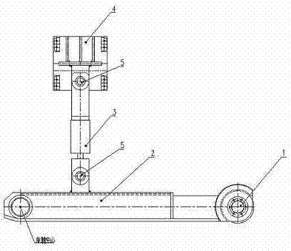
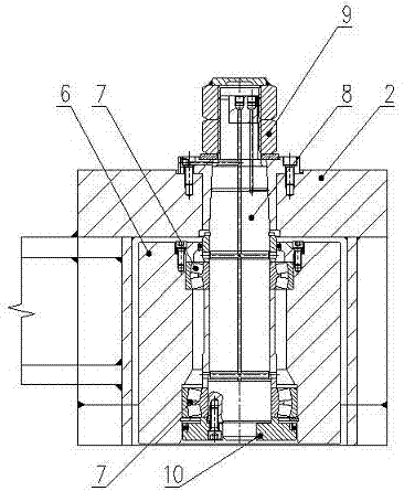
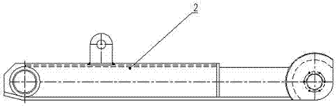
[0023] Example 1: Such as figure 1 — Image 6 , a hydraulic automatic guide device before hydraulic shearing of large bars, comprising a rotating guide wheel mechanism 1, a guide arm 2, a hydraulic cylinder 3, and a hydraulic cylinder base 4, the rotating guide wheel mechanism 1 and the guide arm 2 are assembled together, the The guide arm 2 is connected with the hydraulic cylinder 3 and the hydraulic cylinder 3 and the hydraulic cylinder base 4 through the movable connection structure 5, and the rotating guide wheel mechanism 1 includes a guide wheel 6, a self-aligning roller bearing 7, and a guide wheel. Axle 8, lock nut 9 and end cover 10, the self-aligning roller bearing 7 is located between the guide wheel 6 and the guide wheel shaft 8, the end cover 10 is sleeved on one end of the guide wheel shaft 8, the guide wheel shaft 8 The other end is connected with a lock nut 9, the guide arm 2 is located between the guide wheel 6 and the lock nut 9, the movable connection str...

Embodiment 2

[0024] Example 2: Such as figure 1 — Image 6 , as an improvement of the present invention, the number of the spherical roller bearings 7 is two, which are installed at both ends of the guide wheel 6 respectively. Thereby ensure that the force of the guide wheel 6 is balanced and prolong its service life. The rest of the structures and advantages are exactly the same as in Embodiment 1.

Embodiment 3

[0025] Example 3: Such as figure 1 — Image 6 , as an improvement of the present invention, the stroke of the hydraulic cylinder 3 is controlled by a stroke switch installed next to the driving hydraulic cylinder. According to the size of the intermediate billet, it is only necessary to manually adjust the position of the stroke switch that controls the stroke of the hydraulic cylinder before production. During the working process, the stroke switch will feed back the detected signal to the solenoid valve on the hydraulic valve table for automatic control. The stroke of the hydraulic cylinder. The rest of the structures and advantages are exactly the same as in Embodiment 1.


PUM


Abstract

The invention relates to an automatic front hydraulic guiding device for a big stick hydraulic shear. The automatic front hydraulic guiding device for the big stick hydraulic shear comprises a rotary guiding wheel mechanism, a guiding arm, a hydraulic cylinder and a hydraulic cylinder base; the rotary guiding wheel mechanism and the guiding arm are assembled together; the guiding arm and the hydraulic cylinder and the hydraulic cylinder and the hydraulic cylinder base are connected through a flexible connecting structure; the hydraulic cylinder base is fixed on foundation through a chemical anchor bolt. The integral technical scheme is skillful and practical in design, a rolled piece which smoothly enters the hydraulic shear automatically moves in the same direction along with shear blade actions during cutting of a hydraulic shear blade, bending caused by interference between the rolled piece and a fixed guiding device is avoided, and the rolled piece can smoothly enter a continuous mill to perform production of next procedure. The automatic front hydraulic guiding device for the big stick hydraulic shear is suitable for guiding requirements of middle square billets in various sizes, the continuous mill is guaranteed smoothly clamping blanks all the time, the production efficiency of the continuous mill is obviously improved, the milling pace is quickened, and costs and energy consumption are reduced.

Description

[0001] technical field [0002] The invention relates to a hydraulic automatic guiding mechanism, in particular to a hydraulic automatic guiding device before hydraulic shearing of large bars, and belongs to the technical field of large special steel rolling equipment. Background technique [0003] After the initial rolling of the large bar is completed by the blanking machine, in order to prevent the irregular billets from entering the continuous rolling directly to affect the quality of the product or damage the guides between the racks, hydraulic shears are usually used to cut the head and tail. , but the guide device in front of the existing hydraulic shear is a manual adjustment structure, which cannot move flexibly with the shearing movement of the hydraulic shear, and then causes the head and tail of the sheared billet to bend due to interference with the fixed guide device, making it difficult to enter The tandem rolling mill performs subsequent rolling. Because the...

Claims


Application Information

Patent Timeline
Patent Type & Authority Applications(China)
IPC IPC(8): B23D33/02B21B15/00B21B39/14
Inventor 李彦林李雄刘继贤顾俊杰冯大圣马伟王艳丽武东国
Owner JIANGSU LIANFENG ENERGY EQUIP
Why Eureka
Try Eureka