Method for improving corrosion resistance and wear resistance of optical shaft
A technology of corrosion resistance and wear resistance, applied in the field of optical axis processing, can solve the problems of chrome plating process performance limitations, induced gene mutation, insufficient wear resistance, etc., to improve stability and compactness, and improve fatigue resistance. , the effect of improving corrosion resistance
- Summary
- Abstract
- Description
- Claims
- Application Information
AI Technical Summary
Problems solved by technology
Method used
Image
Examples
Embodiment 1
[0079] Pre-clean the optical shaft made of 45 steel to remove oil and rust on the surface of the optical shaft; preheat the optical shaft at 390°C for 20 minutes, and then infiltrate it with nitrogen, carbon, and lanthanum ionizers at 570°C for 120 minutes; The nitrogen carbon lanthanum ionizing agent comprises the following components by weight percentage: Na 2 CO 3 13%, K 2 CO 3 13%, NaCNO65%, CeCO 3 2%, Li 2 CO 3 6%, La 2 CO 3 1%; after that, it was infiltrated with an ion-activated penetration agent at 530°C for 60 minutes; the ion-activated penetration agent included the following components by weight percentage: Na 2 S0 4 10%, Na 2 CO 3 16%, K 2 CO 3 15%, CO(NH 2 ) 2 45%, K 2 SO 3 2%, CeCO 3 2%, LiOH 5%, KCl 5%; finally, it was infiltrated at 400°C for 30 minutes by oxygen ionolysis agent, and the oxygen ionolysis agent included the following components by weight percentage: Na 2 CO 3 20%, NaNO 2 20%, NaNO 3 40%, CeSO 4 20%;
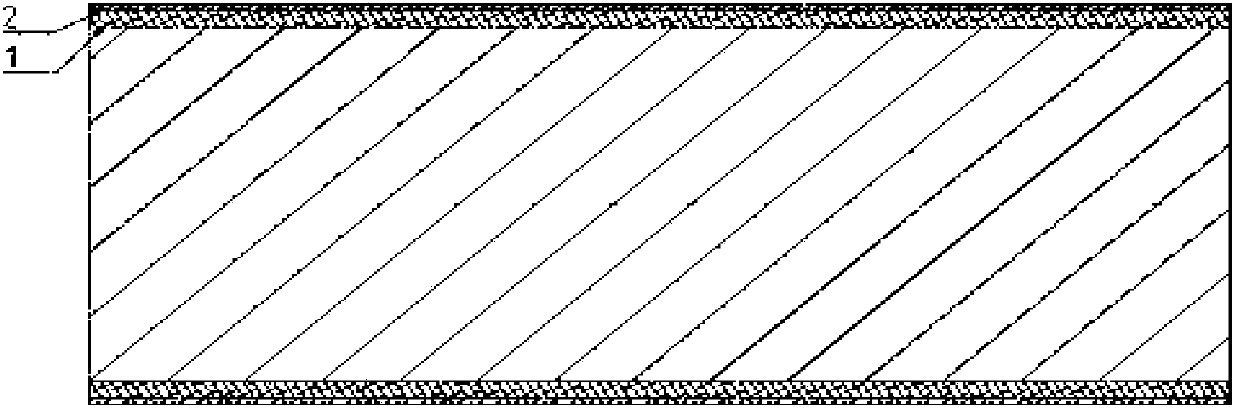
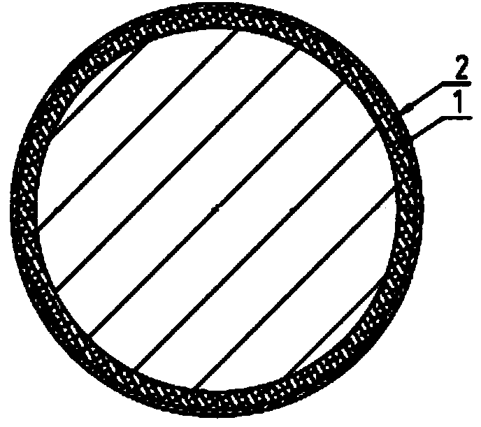
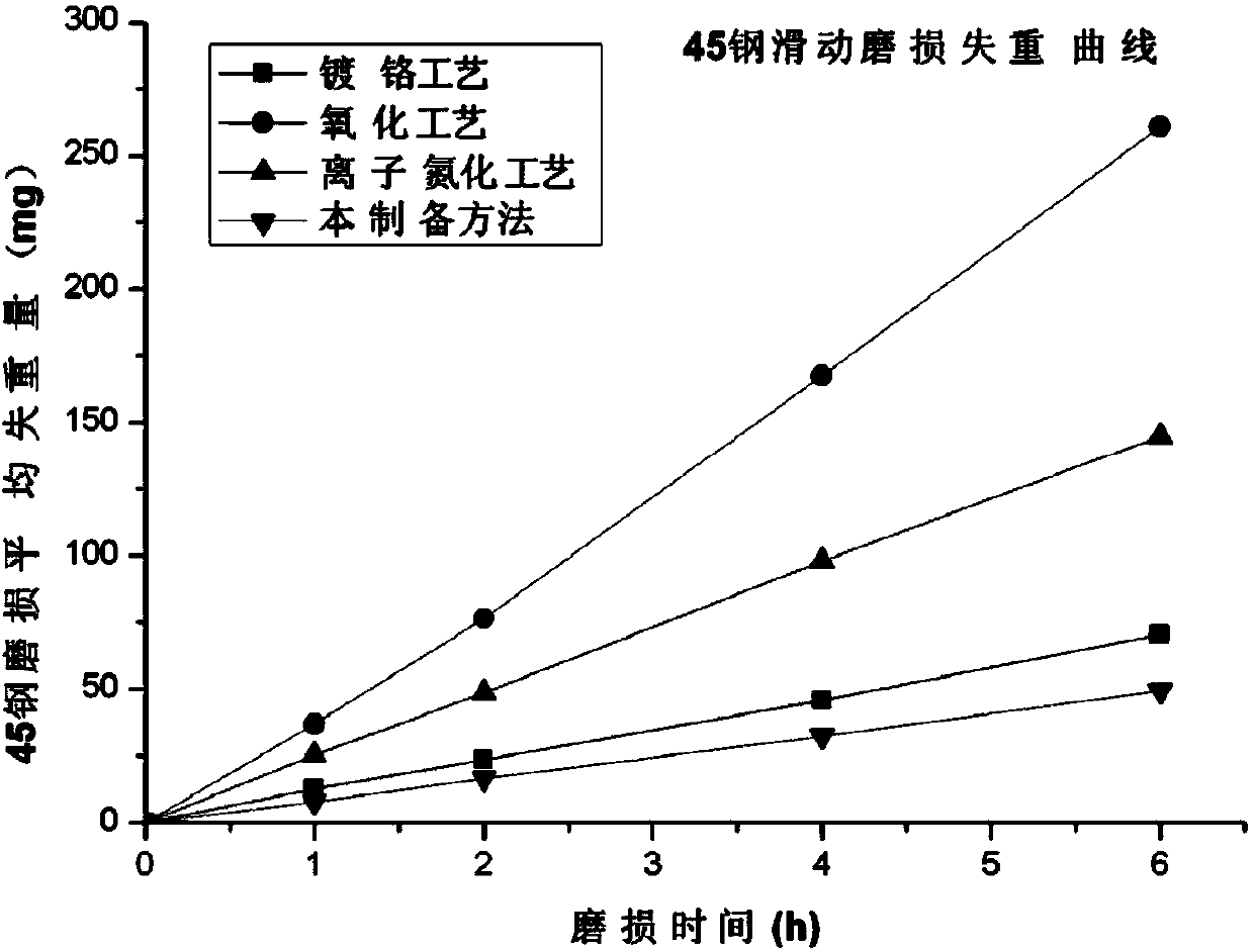
[0080] Such as figur...
Embodiment 2
[0083] Pre-clean the optical shaft made of GCr15 to remove oil and rust on the surface of the optical shaft, preheat the optical shaft at 450°C for 40 minutes, and pass the preheated optical shaft through the nitrogen carbon lanthanum ionizing agent at 590°C Infiltration treatment 90min; Wherein nitrogen carbon lanthanum ion penetration agent comprises the following components by weight percentage: Na 2 CO 3 15%, K 2CO 3 15%, NaCNO60%, CeCO 3 3%, Li 2 CO 3 6.97%, La 2 CO 3 0.03%;
[0084] Then infiltrated with an ion-activated penetration agent at 550°C for 90 minutes; the ion-activated penetration agent includes the following components by weight percentage: Na 2 SO 4 5%, Na 2 CO 3 20%, K 2 CO 3 14%, CO(NH 2 ) 2 30%, K 2 SO 3 3%, CeCO 3 3%, LiOH10%, KCl15%;
[0085] Afterwards, the optical axis was infiltrated with an oxygen ionizer at 430°C for 30 minutes; the oxygen ionizer included the following components by weight percentage: Na 2 CO 3 30%, NaNO 2 3...
Embodiment 3
[0089] Pre-clean the optical shaft made of 40MnV to remove oil and rust on the surface of the optical shaft. Preheat the optical shaft at 400°C for 30 minutes; Process 80min; Wherein the nitrogen carbon lanthanum ionizing agent comprises the following components by weight percentage: Na 2 CO 3 12%, K 2 CO 3 20%, NaCNO57%, CeCO 3 3%, Li 2 CO 3 7.95%, La 2 CO 3 0.05%;
[0090] Then the optical axis treated in the above steps is infiltrated at 500° C. for 100 minutes through the ion-activated penetrating agent; the ion-activated penetrating agent includes the following components by weight percentage: Na 2 SO 4 8%, Na 2 CO 3 10%, K 2 CO 3 20%, CO(NH 2 ) 2 41%, K 2 SO 3 2%, CeCO 3 2%, LiOH7%, KCl10%;
[0091] Then, the optical axis is infiltrated with oxygen ionizer at 400°C for 20 minutes. The oxygen ionizer includes the following components by weight percentage: Na 2 CO 3 25%, NaNO 2 25%, NaNO 3 32%, CeSO 4 18%;
[0092] Such as figure 1 with figure 2...
PUM
| Property | Measurement | Unit |
|---|---|---|
| thickness | aaaaa | aaaaa |
| hardness | aaaaa | aaaaa |
| thickness | aaaaa | aaaaa |
Abstract
Description
Claims
Application Information
 - R&D Engineer
- R&D Manager
- IP Professional
- Industry Leading Data Capabilities
- Powerful AI technology
- Patent DNA Extraction
Browse by: Latest US Patents, China's latest patents, Technical Efficacy Thesaurus, Application Domain, Technology Topic, Popular Technical Reports.
© 2024 PatSnap. All rights reserved.Legal|Privacy policy|Modern Slavery Act Transparency Statement|Sitemap|About US| Contact US: help@patsnap.com


