Injection molding system for improving injection molding accuracy in mold injection

An injection molding system and accuracy technology, applied in the field of injection molding system, can solve the problems of contact error, error, melt plastic outflow, etc. between the barrel and the molding mechanism, so as to solve the error of mechanical vibration or transmission, the contact is tight and the contact is accurate Effect

Inactive Publication Date: 2014-12-03
CHENGDU HENGTONG ZHAOYE PRECISION MACHINERY
View PDF6 Cites 2 Cited by
  • Summary
  • Abstract
  • Description
  • Claims
  • Application Information

AI Technical Summary

Problems solved by technology

[0003] The purpose of the present invention is to overcome the above-mentioned existing mechanical vibration or transmission errors, which often lead to errors in the contact between the barrel and the molding mechanism, causing the molten plastic to flow out. System, the system utilizes the large-scale cooperation between the conical frustum and the pit, combined with the precise cooperation between the annular boss and the annular groove, so that the barrel and the forming mechanism are in close and precise contact, avoiding the outflow of the melt, and solving the existing problem Mechanical vibration or transmission errors often lead to errors in the contact between the barrel and the molding mechanism, resulting in the problem of molten plastic flowing out

Method used


Image

  • Injection molding system for improving injection molding accuracy in mold injection

Examples


Embodiment 1

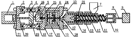
[0012] like figure 1 As shown, the injection molding system that improves the accuracy of injection molding in mold injection molding includes a power mechanism, an injection mechanism 7, a feeding mechanism, a molding mechanism 6, a demoulding mechanism and a demoulding power mechanism, and the power mechanism, the feeding mechanism, and the molding mechanism 6 , the demoulding mechanism and the demoulding power mechanism are connected sequentially, and the injection mechanism 7 is connected with the feeding mechanism; the feeding mechanism includes an internally hollow barrel 12, and the injection mechanism 7 communicates with the interior of the barrel 12, and the barrel 12 is provided with a screw rod 11 , the outer wall of the screw 11 is fitted with a spiral joint 22, the spiral joint 22 is arranged inside the barrel 12, and one end of the screw 11 is connected to the power mechanism, and the other end of the screw 11 faces the forming mechanism 6 and has a gap with the e...


PUM


Abstract

The invention discloses an injection molding system for improving injection molding accuracy in mold injection. A power mechanism, a feed mechanism, a forming mechanism, a de-molding mechanism and a de-molding power mechanism are orderly connected. An injection molding mechanism is connected with the feed mechanism. The injection molding mechanism is communicated with the interior of a charging barrel. A screw is arranged in the charging barrel. A spiral joint is sleeved on the outer wall of the screw. The screw is connected with the power mechanism. The screw is sleeved with a non-return valve. The non-return valve is connected with the charging barrel in a seamless way. The charging barrel is sleeved with a heater. The charging barrel is connected with a cone table. The cone table is communicated with the interior of the charging barrel to form an integrated structure. The cone table is indented to form a circular groove. The forming mechanism is indented to form a pit. The cone table contacts the pit in a seamless way. The pit bulges to form a circular boss. A circular boss wall contacts the circular groove. The circular boss contacts the circular groove. By matching the cone table with the pit in a large scale, and accurately matching the circular boss with the circular groove, the system enables the charging barrel to contact the forming mechanism tightly and accurately and avoids outflow phenomenon of the melt.

Description

technical field [0001] The invention relates to an injection molding system, in particular to an injection molding system for improving injection molding accuracy in mold injection molding. Background technique [0002] A mold is a tool used to shape objects, which is composed of various parts. It mainly realizes the processing of the shape of the article through the change of the physical state of the formed material. It is usually used in industry to obtain various molds and tools for required products by injection molding, blow molding, extrusion, die casting or forging forming, smelting, stamping, stretching and other methods. There are many types of molds, which can be divided into molds for metal processing and molds for non-metal and powder metallurgy according to the processing objects and processing technology. According to the different molding materials, molds can be divided into metal molds, plastic molds, and special molds. According to the structural charact...

Claims


Application Information

Patent Timeline
Patent Type & Authority Applications(China)
IPC IPC(8): B29C45/76B29C45/62B29C45/26
CPCB29C45/62B29C45/2606
Inventor 吴光武
Owner CHENGDU HENGTONG ZHAOYE PRECISION MACHINERY
Why Eureka
Try Eureka