
Airbag device

a technology of airbags and airbags, which is applied in the direction of pedestrian/occupant safety arrangements, vehicular safety arrangements, vehicle components, etc., can solve the problems of inability to perform suitable airbag expansion, complicated airbag research and development or manufacturing stages, and limited movement of the occupant's part to the forward side of the vehicle, so as to prevent excessive airbag inflation

Active Publication Date: 2012-03-22
NIHON PLAST CO LTD
View PDF2 Cites 26 Cited by
  • Summary
  • Abstract
  • Description
  • Claims
  • Application Information

AI Technical Summary

Benefits of technology

[0064]The airbag according to the present invention has the configuration as described above, and thus, has advantageous effects described below.[0065](1) The airbag of the present invention is structured to open, close, and open a gas evacuation hole for evacuating a redundant gas in order to achieve airbag inflation and expansion suitable for occupant, a pulling member that is a base cloth valve is formed by a first mount portion and a second mount portion, whereby tension of the gas evacuation hole can be concentrated at a predetermined site, outflow of the gas from the gas evacuation hole can be restrained, and suitable airbag expansion can be stably performed.[0066](2) By providing a pulling protection member, the pulling member is prevented from floating at the time of airbag expansion, and gas outflow can be restrained to achieve more suitable airbag expansion.[0067](3) The pulling member can be configured by linearly cutting a base cloth at the time of manufacture of an airbag, thus improving yields.[0068](4) A first mount portion and a second mount portion of the pulling member are mounted in an airbag after these mount portions have been divided into a plurality of ways (for example, after the second mount portion has been divided into two ways); and therefore, a two-way portion of the pulling member can be mounted while being kept away from a suspension cord for preventing excessive inflation of the airbag, the suspension cord being generally provided in the airbag.
[0065](1) The airbag of the present invention is structured to open, close, and open a gas evacuation hole for evacuating a redundant gas in order to achieve airbag inflation and expansion suitable for occupant, a pulling member that is a base cloth valve is formed by a first mount portion and a second mount portion, whereby tension of the gas evacuation hole can be concentrated at a predetermined site, outflow of the gas from the gas evacuation hole can be restrained, and suitable airbag expansion can be stably performed.
[0066](2) By providing a pulling protection member, the pulling member is prevented from floating at the time of airbag expansion, and gas outflow can be restrained to achieve more suitable airbag expansion.
[0067](3) The pulling member can be configured by linearly cutting a base cloth at the time of manufacture of an airbag, thus improving yields.
[0068](4) A first mount portion and a second mount portion of the pulling member are mounted in an airbag after these mount portions have been divided into a plurality of ways (for example, after the second mount portion has been divided into two ways); and therefore, a two-way portion of the pulling member can be mounted while being kept away from a suspension cord for preventing excessive inflation of the airbag, the suspension cord being generally provided in the airbag.

Problems solved by technology

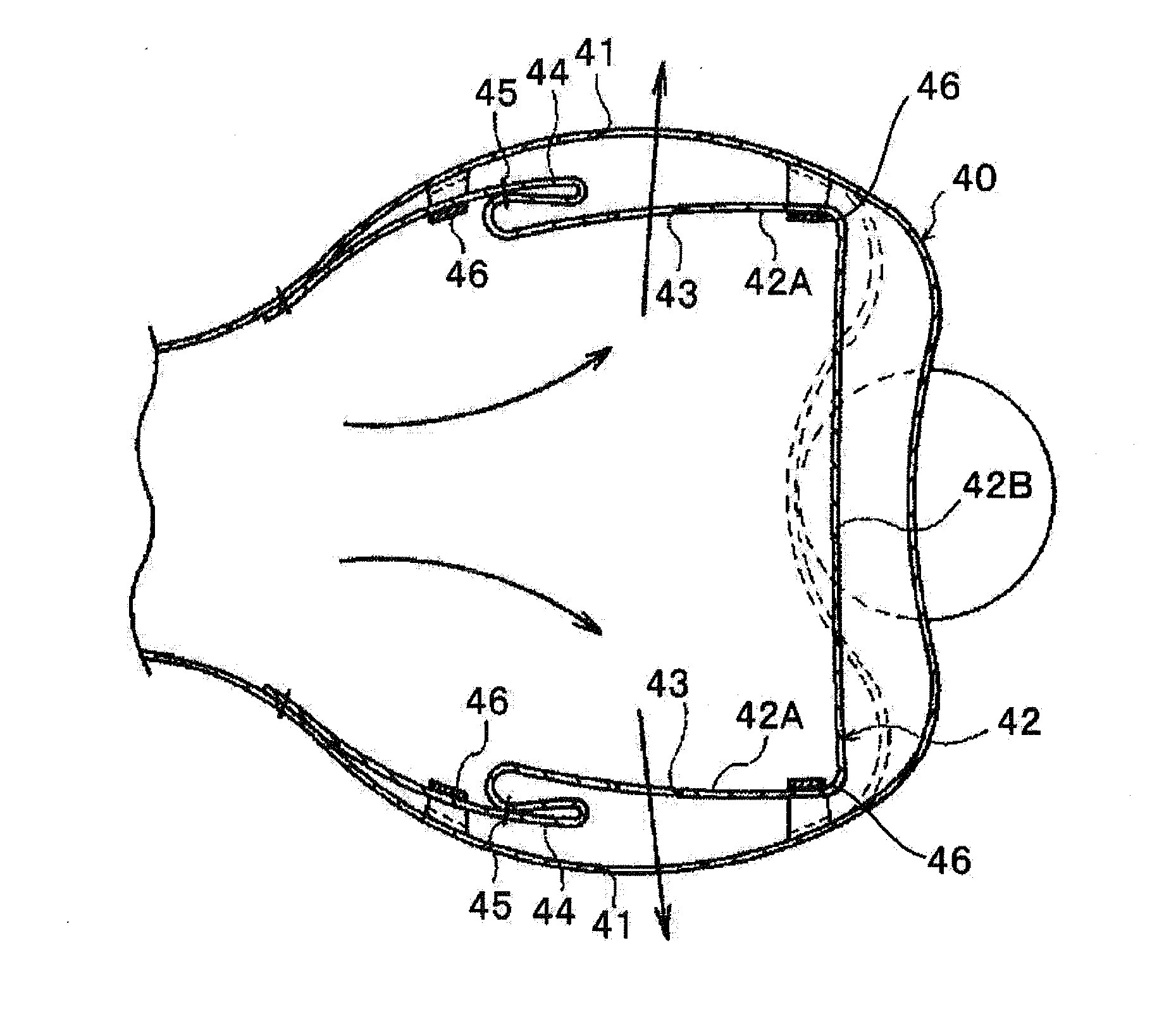
When the airbag 40 for passenger seat has inflated and expanded, in a case where occupant has taken a seatbelt, an upper part of the body including the occupant's head is constrained by means of the seatbelt, and thus, the quantity of movement of the occupant's part to the forward side of the vehicle is limited.
However, Japanese Unexamined Patent Application Publication No. 2009-196551 described above fails to disclose or suggest a solution or construction for prevention of a problem with twisting of the side portions 42A.
However, in the linear base cloth valve, the base cloth valve is thinned due to breakage or twisting of the base cloth valve at the time of the maximum inflation and expansion of an airbag, the gas evacuation hole is not well closed, and there is a possibility that suitable airbag expansion cannot be performed.
Therefore, there is a need to contrive a preferred folding method or a means for smoothing movement of the base cloth valve, airbag research and development or manufacturing stage becomes complicated, and there has been a problem associated with a higher cost.

Method used


Image

  • Airbag device
  • Airbag device
  • Airbag device

Examples


first embodiment

[0084]A construction of an airbag main body 10 according to the present invention will be described with reference to FIG. 1 to FIG. 5. An inflator mount portion 13 in the airbag main body 10 is shown, although an inflator that is arranged at a back face side of the airbag main body 10 is not shown.

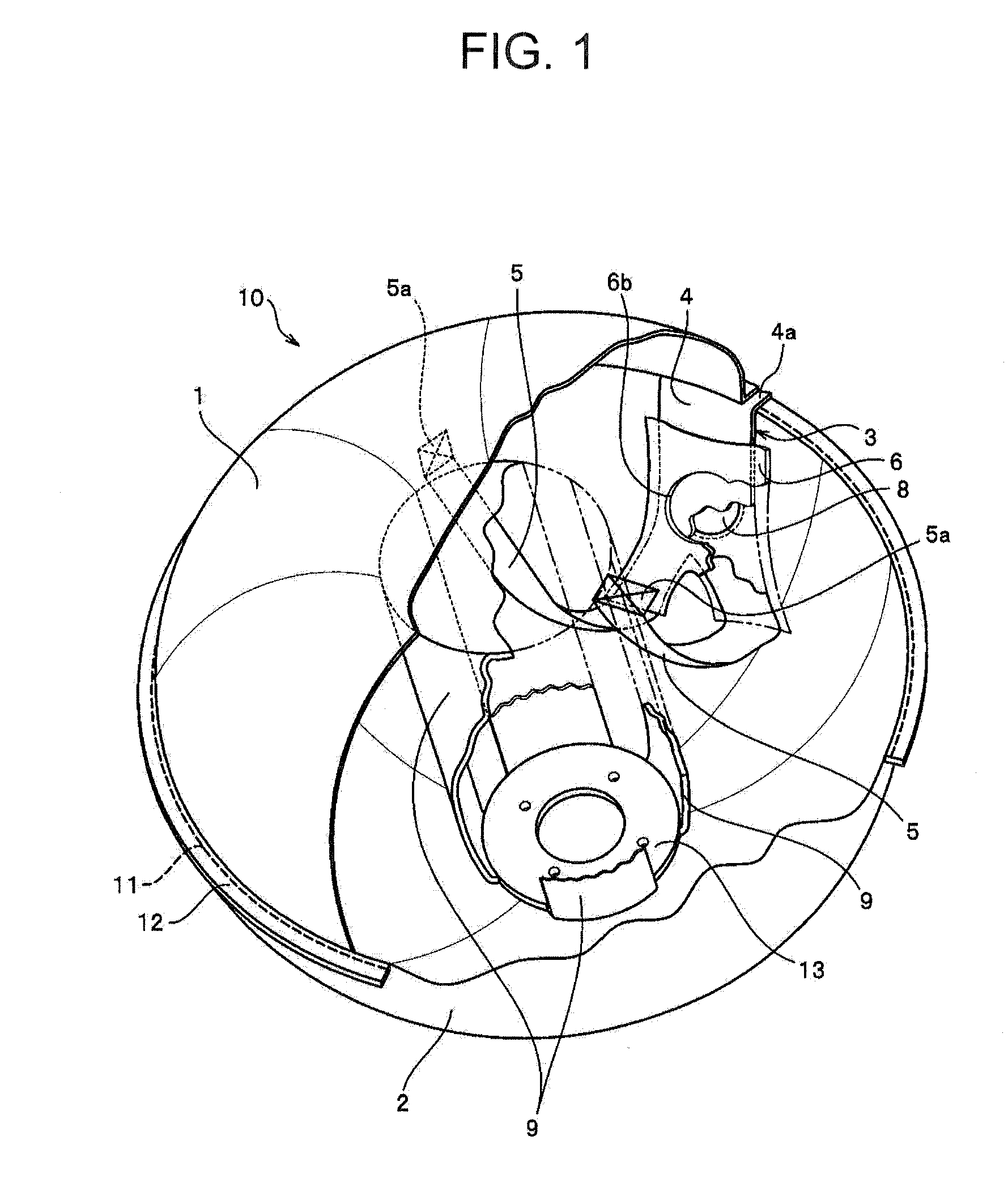
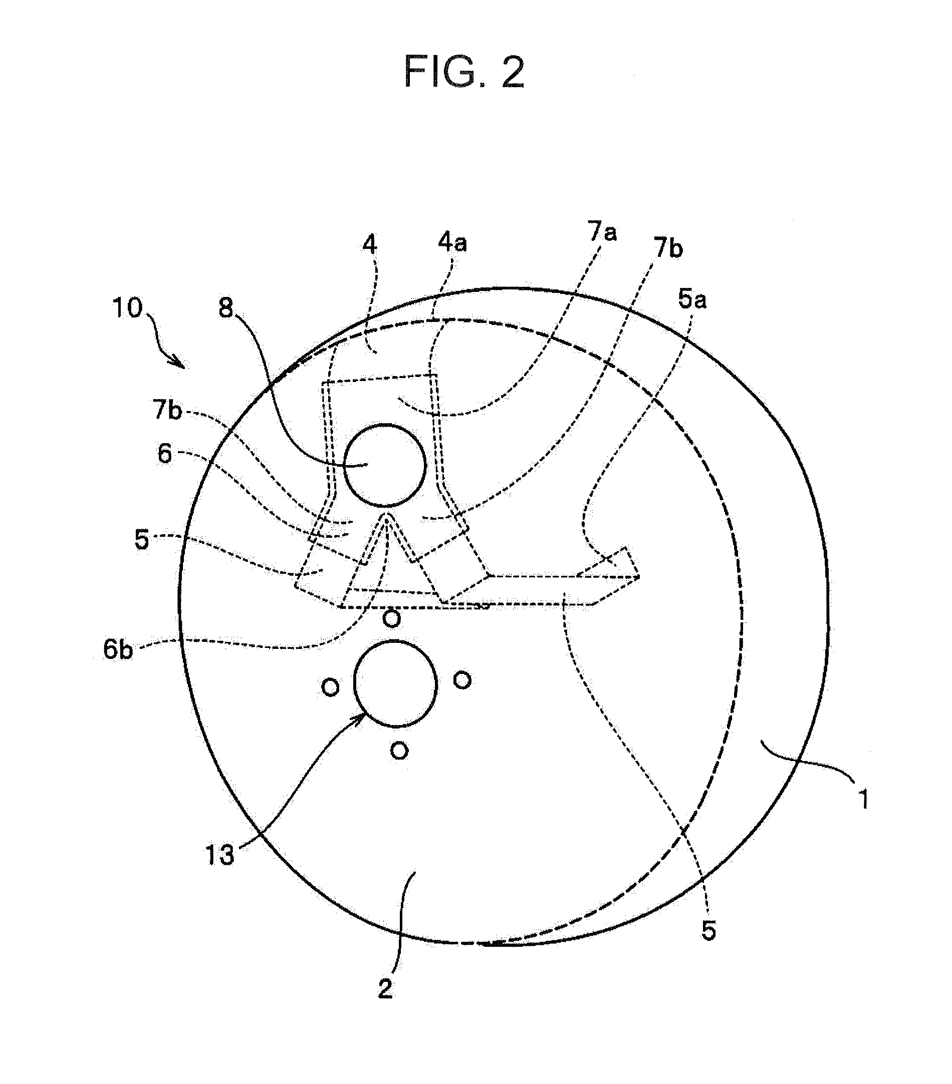
[0085]As shown in FIG. 1, in the airbag main body 10, an outer circumferential edge of a main panel 2 at a wind shield side and an outer circumferential edge of a main panel 1 at an occupant constraint face side are superimposed on an ear portion 12, and the ear portion 12 is sewn at a sewing portion 11. An inflator, although not shown, is configured to be mountable on an inflator mount portion 13 that is provided on the main panel 2. On the main panel 2, a vent hole 8 is formed, and in the airbag main body 10, a rectification cloth 3 configured to open or close the vent hole 8 is provided. The airbag main body 10 is constructed with the main panel 1 and the main panel 2.

[0086]The airbag ...

second embodiment

[0114]Hereinafter, a second embodiment of the present invention will be described as another embodiment.

[0115]First, the second embodiment of the present invention will be generally described.

[0116]In the linear base cloth valve of the related art, there is a possibility that the base cloth valve becomes thin due to folding or distortion of the base cloth valve at the time of the maximum inflation and expansion of an airbag, and contrivance is required to stably and easily make an opening or closing operation of a gas excavation hole. Therefore, the airbag according to the present invention, as shown in FIG. 12, has: a gas excavation hole 3A; and a pulling member 4A configured to open or close the gas evacuation hole 3A, and has a first mount portion 6A of an occupant-side airbag portion 2A; a second mount portion 7A of a vehicle-side airbag portion 1A; and a closed portion that is disposed to be able to be superimposed on the gas evacuation hole 3A. The pulling member 4A is moved t...


PUM


Abstract

The present invention provides an airbag device that is capable of restraining a rectification cloth that switches a vent hole to an opened or closed state so as not to be twisted, and that is capable of switching the vent hole from an opened state to a closed state, and further, switching to the opened state. At an initial stage at which an airbag main body inflates and expands, the vent hole 8 is arranged between the leg portions 5, and when the airbag main body is in a predetermined internal pressure state, the vent hole is closed by means of the band-shaped portion 4. If an occupant or the like comes into contact with the airbag main body, a tense state of each of the leg portions is released, the rectification cloth is established in a slackened state, and the vent hole 8 is established in an opened state.

Description

CROSS-REFERENCE TO RELATED APPLICATIONS[0001]This application claims priority of Japanese Patent Application No. 2010-211959, filed on Sep. 22, 2010 and Japanese Patent Application No. 2010-266693, filed in Nov. 30, 2010. The contents of this application are incorporated herein by reference in their entirety.BACKGROUND OF THE INVENTION[0002]1. Field of the Invention[0003]The present invention relates to an airbag device having an airbag that is capable of being inflated and expanded by means of a gas that is supplied from a gas generator such as an inflator if a collision of a vehicle or the like occurs. In particular, the present invention relates to an airbag device that is capable of preventing twisting of a tether configured to open or close a vent hole; that is capable of making inflation and expansion speedily while restraining gas evacuation from the airbag at an initial stage at which the airbag inflates and expands to thereby set an inside of the airbag at a predetermined i...

Claims


Application Information

Patent Timeline
IPC IPC(8): B60R21/30
CPCB60R21/239B60R2021/2395B60R2021/23382
Inventor SUZUKI, MASATOIWAMOTO, HIROYUKI
Owner NIHON PLAST CO LTD
Learn More