Display device with suspended ferroelectric particles
A technology for electrophoretic display and equipment, which can be used in instruments, nonlinear optics, optics, etc., and can solve problems such as spatial resolution limitations
- Summary
- Abstract
- Description
- Claims
- Application Information
AI Technical Summary
Problems solved by technology
Method used
Image
Examples
example (1
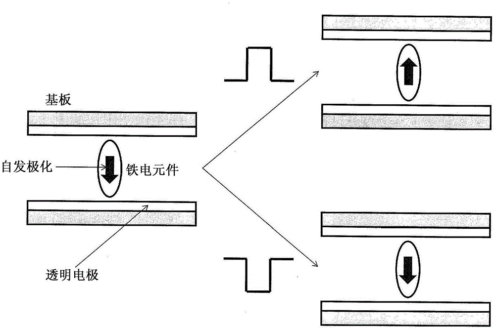
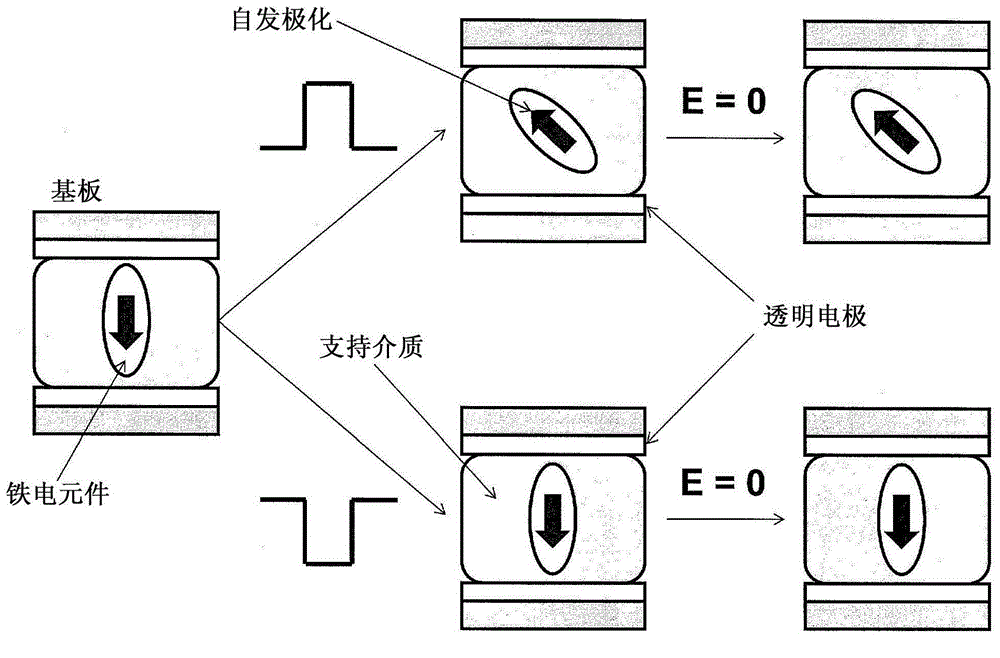
[0148] A ferroelectric PVDF sheet with a thickness of 40 pm was used. TiO 2 The dispersible sheet is laminated on the surface of the PVDF sheet. TiO 2 The dispersible tablet was 10 microns thick with the base tablet material made of polyethylene. This laminate was cut into squares with an average size of 200 μm*200 μm by using a sharp square stainless steel sheet. For the thixotropic suspending medium, 5 centistokes of silicon fluid (Aldrich Chemical Company) and fumed silica flakes were mixed in a weight ratio of 5 to 1. After the two were completely mixed, 5% by weight of the above-prepared PVDF particle excised portion was mixed with the thixotropic fluid. The original PVDF sheet has 15nC / cm 2 spontaneous polarization.
[0149] This mixture forms a very viscous colloidal fluid. In order to stabilize the fluid, after leaving the fluid at room temperature for 24 hours, the fluid was moved to the next step of the experiment. Color filter glass substrates based on both ...
example (2
[0157] A ferroelectric PVDF sheet with a thickness of 40pm was used. A carbon based dyed dispersant sheet was laminated on one surface of the PVDF sheet. The carbon disperse sheet is 10 microns thick, where the base sheet material is made of polyethylene. Cut the laminate into squares of average size 200 μm*200 μm by using a sharp square stainless steel sheet. For the thixotropic suspending medium, 5 cmS of silicon fluid (Aldrich Chemical Co.) and fumed silica flakes were mixed in a 5 to 1 weight ratio. After the two were completely mixed, 5% by weight of the above-prepared PVDF particle excised portion was mixed with the thixotropic fluid. The original PVDF sheet has 12nC / cm 2 spontaneous polarization.
[0158] This mixture forms a very viscous colloidal fluid. In order to stabilize the fluid, after leaving the fluid at room temperature for 24 hours, the fluid was moved to the next step of the experiment. Red, blue and green color filters were used together with transpa...
example (3
[0164] A ferroelectric PVDF sheet with a thickness of 40pm was used. The PVDF sheet has its own spontaneous polarization direction perpendicular to the sheet surface, and the same TiO 2 The dispersant sheet is laminated on one surface of the PVDF sheet, which is the negative polarization direction. TiO 2 The dispersible tablet was 10 microns thick with the base tablet material made of polyethylene. The same carbon-based dyed disperse sheet as in Example 2 was laminated on the other surface of PVDF, which was positively charged. Both surfaces of PVDF are laminated with white flakes and black flakes. This laminate was cut into squares with an average size of 200 μm*200 μm by using a sharp square stainless steel sheet. For the thixotropic suspending medium, 5 centistokes of silicon fluid (Aldrich Chemical Company) and fumed silica flakes were mixed in a weight ratio of 5 to 1. After the two were completely mixed, 5% by weight of the excised portion of the PVDF particles prep...
PUM
| Property | Measurement | Unit |
|---|---|---|
| thickness | aaaaa | aaaaa |
| reflectance | aaaaa | aaaaa |
Abstract
Description
Claims
Application Information
 - Generate Ideas
- Intellectual Property
- Life Sciences
- Materials
- Tech Scout
- Unparalleled Data Quality
- Higher Quality Content
- 60% Fewer Hallucinations
Browse by: Latest US Patents, China's latest patents, Technical Efficacy Thesaurus, Application Domain, Technology Topic, Popular Technical Reports.
© 2025 PatSnap. All rights reserved.Legal|Privacy policy|Modern Slavery Act Transparency Statement|Sitemap|About US| Contact US: help@patsnap.com


