Positioning grip for a mobile electronic device

Inactive Publication Date: 2013-08-15
OCTA
View PDF27 Cites 70 Cited by
  • Summary
  • Abstract
  • Description
  • Claims
  • Application Information

AI Technical Summary

Benefits of technology

The patent describes a gripping device that can hold an electronic device and also function as a stand to position the device at different viewing angles. The device has a comfortable shape and is easy to use. It can be interconnected to a horizontal or vertical surface using a suctioning dock, clamp, or other means. The device can be designed for portrait or landscape viewing and can be used on automobiles or airplanes. The device also has a support that allows the electronic device to be moved in three degrees of freedom. Overall, the gripping device offers a versatile and efficient way to hold and position electronic devices.

Problems solved by technology

One drawback of these devices is that their size, shape and / or surface texture often renders them difficult to hold and tilt to an acceptable viewing angle.
Those familiar with such devices will appreciate that after time, the user may become fatigued, which results in the reduction of holding force and associated stability.
Holding an electronic device also does not permit the use of one or both hands for other activities that may be related to the functions being performed by an electronic device, e.g. typing.
Further, some electronic devices are small, sleek, and have smooth surfaces, and are thus difficult to grasp.

Method used


Image

  • Positioning grip for a mobile electronic device
  • Positioning grip for a mobile electronic device
  • Positioning grip for a mobile electronic device

Examples


Embodiment Construction

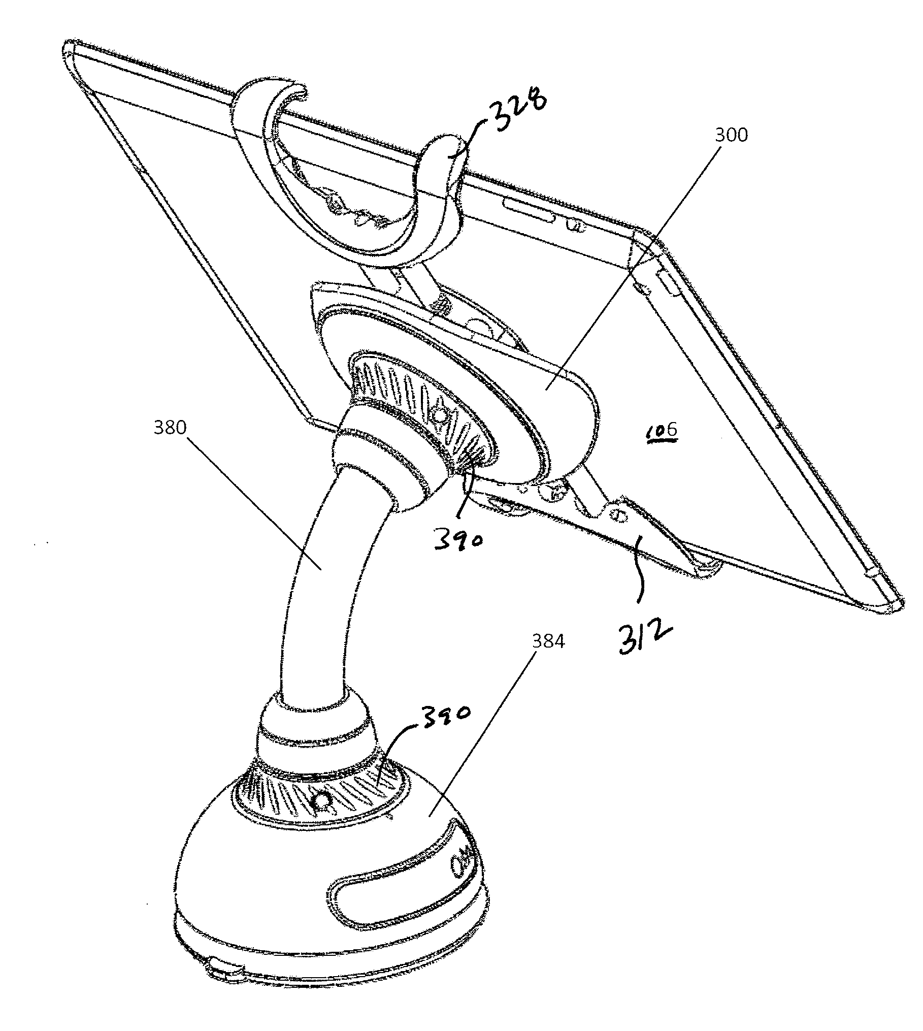
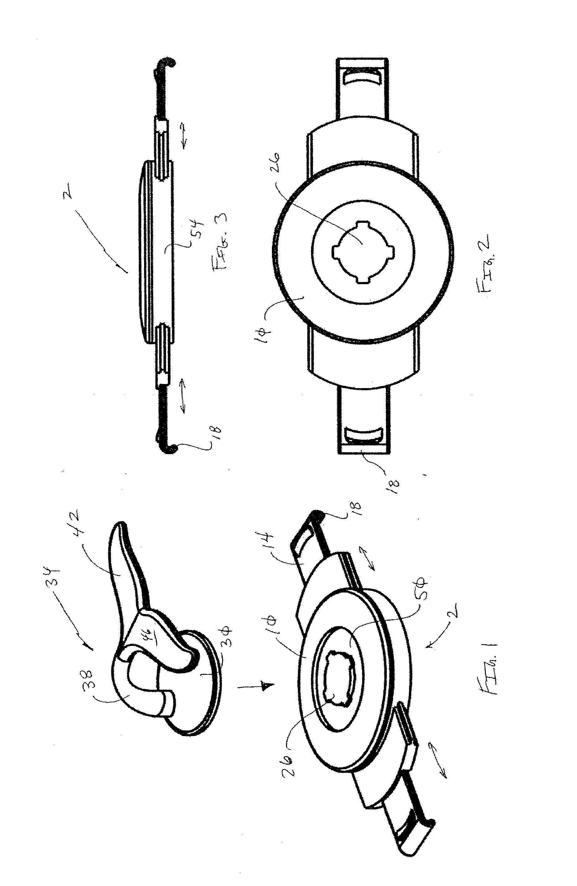
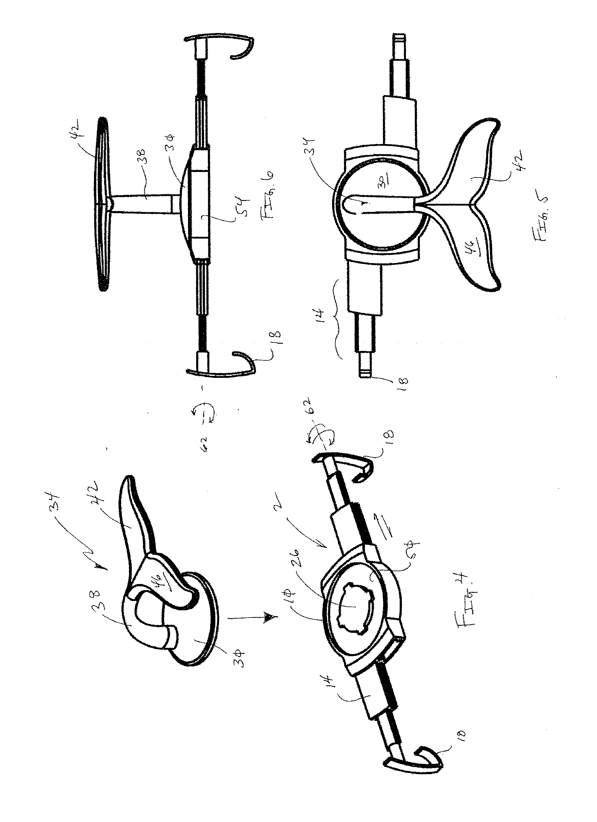
[0080]Referring now to FIGS. 1-25, an electronic device interface 2 is provided that selectively interconnects to an electronic device 6. The electronic device interface 2 is generally comprised of a dock portion 10 with selectively adjustable arms 14. The arms 14 end in fingers 18 that engage edges 22 or corners of the electronic device 6, which secures the electronic device interface 2 to the electronic device 6. To view the electronic device, a user can simply hold the interface. Alternatively, the dock portion 10 includes a fitting 26 that selectively mates with a complimentary fitting of a base portion 30 of a positioning grip 34. The positioning grip 34 further includes a stem 38 that is interconnected to a support 42. One of skill in the art will appreciate that although a bayonet type fitting is shown, other types of selective interconnection systems may be employed without departing from the scope of the invention, such as click lock, magnets, suction, or other selectively ...


PUM

PropertyMeasurementUnit
Selectivityaaaaaaaaaa

Abstract

An electronic device interface is provided that is selectively interconnectable to a portable electronic device. The interface is preferably interconnected to the portable electronic device via inwardly-biased arms that end in fingers that engage opposing edges or corners of the portable electronic device. The interface may receive a positioning grip that includes a support having at least one selectively deflectable surface.

Description

[0001]This application is a Continuation-In-Part of PCT application No. PCT / US2011 / 045921, filed with the WIPO on Jul. 29, 2011, which designates the United States, and which claims the benefit of U.S. Provisional Patent Application Ser. No. 61 / 503,240, filed Jun. 30, 2011, U.S. Provisional Patent Application Ser. No. 61 / 424,973, filed Dec. 20, 2010, U.S. Provisional Patent Application Ser. No. 61 / 400,520, filed Jul. 29, 2010, and U.S. Provisional Patent Application Ser. No. 61 / 414,747, filed Nov. 17, 2010, the entire disclosures of which are incorporated by reference herein.[0002]This application also claims the benefit of U.S. Provisional Patent Application Ser. No. 61 / 709,321, filed Oct. 3, 2012, the entire disclosure of which is incorporated by reference herein.FIELD OF THE INVENTION[0003]Embodiments of the present invention generally relate to a device for selective interconnection to a mobile electronic device to enhance the use thereof. More specifically, one embodiment of th...

Claims


Application Information

Patent Timeline
IPC IPC(8): F16M13/02
CPCF16M11/041F16M11/10F16M11/40F16M13/00Y10T29/49826F16M13/022F16M11/105F16M2200/028F16M13/04
Inventor TROTSKY, KEVIN
Owner OCTA
Why Eureka
Try Eureka