Vehicle control device and method therefor

Active Publication Date: 2018-07-26
LG ELECTRONICS INC
View PDF0 Cites 24 Cited by
  • Summary
  • Abstract
  • Description
  • Claims
  • Application Information

AI Technical Summary

Benefits of technology

The present invention provides a vehicle control device and method that ensures stability in controlling functions of a vehicle and displaying various functions and information related to the vehicle based on the needs of the user. The device allows users to more freely utilize the display unit by managing and displaying different functions independently. The device also allows users to control the entire area of the touch screen based on their selection, state of the vehicle or driving state of the operating system program. Overall, the invention provides a more efficient and effective user experience in controlling and utilizing the vehicle's functions.

Problems solved by technology

On the other hand, the diversification of the functions available in the vehicle requires a CPU of a vehicle control device to handle a more complicated and larger amount of operation.
However, due to the structural characteristics caused in a structure of the complicated vehicle control device, safety is inevitably lowered, compared with the use of simple functions, and in terms of characteristics of the vehicle control device, a degradation of safety may cause a high risk.
In this case, however, each CPU is completely independently driven to require separate hardware resources, i.e., a memory, a display, etc., thus incurring excessive cost.
In addition, since each of the CPUs is driven separately, repeated tasks such as detecting a state of a vehicle are separately handled, or tasks processed in each CPU conflicts with each other.
Also, in order to exchange information between the CPUs, information must be exchanged through a data transfer unit such as a bus connected between the CPUs, and thus, an amount of exchanged information is limited according to a limited bandwidth, resulting in difficulty in free utilization of the display.

Method used


Image

  • Vehicle control device and method therefor
  • Vehicle control device and method therefor
  • Vehicle control device and method therefor

Examples


Embodiment Construction

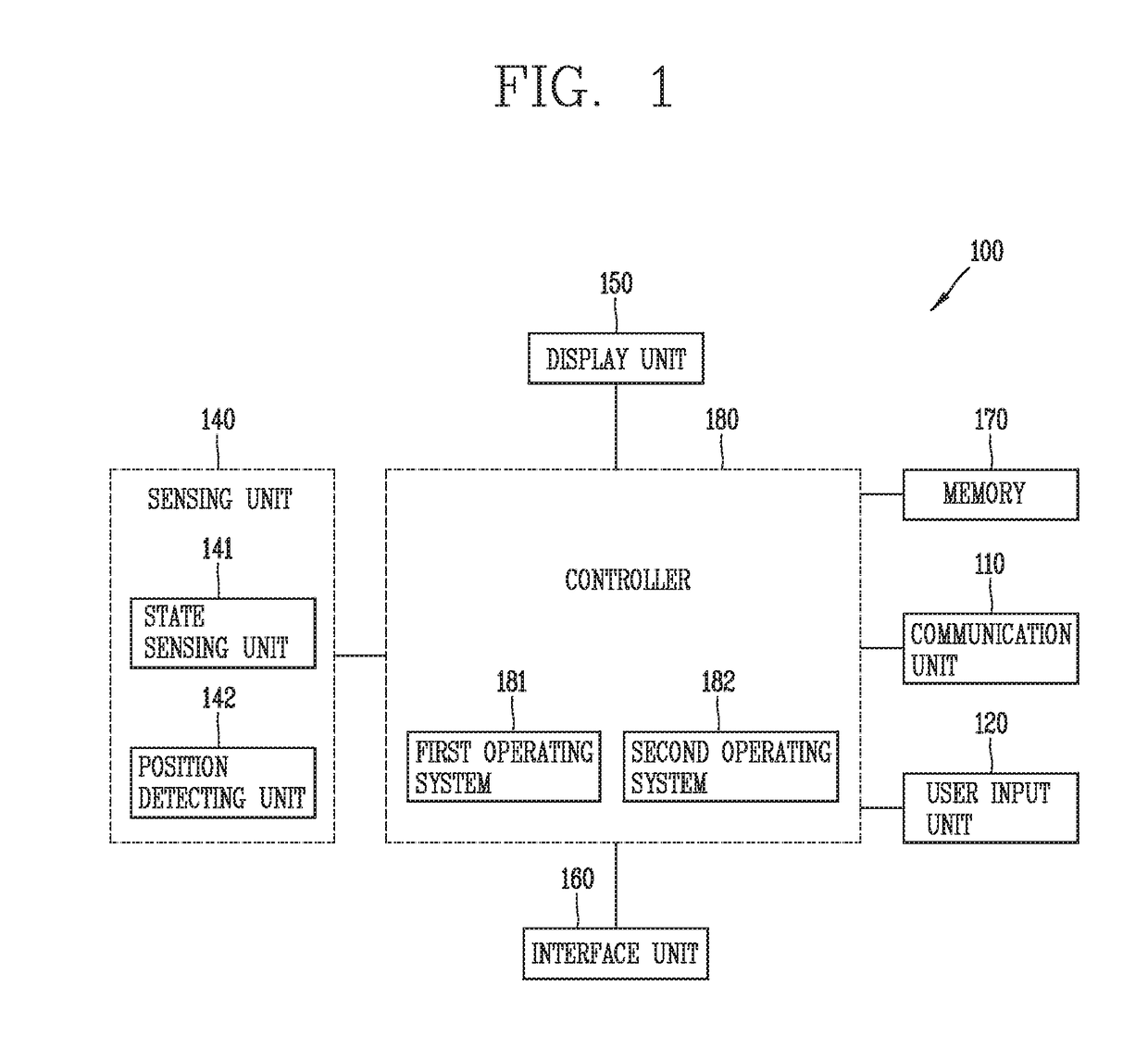
[0044]Description will now be given in detail according to exemplary embodiments disclosed herein, with reference to the accompanying drawings. For the sake of brief description with reference to the drawings, the same or equivalent components may be provided with the same or similar reference numbers, and description thereof will not be repeated. In general, a suffix such as “module” and “unit” may be used to refer to elements or components. Use of such a suffix herein is merely intended to facilitate description of the specification, and the suffix itself is not intended to give any special meaning or function. In the present disclosure, that which is well-known to one of ordinary skill in the relevant art has generally been omitted for the sake of brevity. The accompanying drawings are used to help easily understand various technical features and it should be understood that the embodiments presented herein are not limited by the accompanying drawings. As such, the present disclo...


PUM


Abstract

The present invention relates to a vehicle control device that can display various pieces of image information associated with a state of a vehicle, and a control method for the device. The vehicle control device comprises: a single touch screen; and a single control unit, which includes at least two different operating system programs which independently operate, and controls each of the operating system programs to display image information on the single touch screen, wherein the control unit controls the touch screen to enable at least one of the operating system programs to display image information on the touch screen, according to at least one of operation states of the operating system programs and the state of the vehicle.

Description

TECHNICAL FIELD[0001]The present invention relates to a vehicle control device capable of displaying various image information related to a state of a vehicle and a method for controlling the same.BACKGROUND ART[0002]Unlike the conventional technology, the current vehicle control technology allows a vehicle to provide a variety of functions to a user. Accordingly, image information on various functions that may be provided is displayed through a display unit provided inside the vehicle and the user can check various states, functions, navigation information; and the like, of the vehicle based on the displayed image information.[0003]On the other hand, the diversification of the functions available in the vehicle requires a CPU of a vehicle control device to handle a more complicated and larger amount of operation. As technologies have been developed, CPUs are more highly integrated and have high performance and hardware characteristics meet the demand. However, due to the structural...

Claims


Application Information

Patent Timeline
IPC IPC(8): B60K37/02B60K35/00B60W50/14G06F3/0488
CPCB60K35/00B60W50/14G06F3/0488B60W2050/146B60K2350/1028B60K2350/1072B60K2350/352B60K2350/357B60K2350/901B60K2350/908B60K37/02B60W50/10B60W2520/10B60W2554/00B60W2555/20B60K35/10B60K2360/1438B60K35/20B60K2360/151B60K35/60B60K35/213B60K35/81B60K35/85B60K2360/589B60K35/654
Inventor KIM, SUJINBAEK, BUMHYEONJUN, HONGGUL
Owner LG ELECTRONICS INC
Why Eureka
Try Eureka