
Power cable

A power cable, semi-conductive technology, applied in the direction of power cables with shielding layer/conductive layer, insulated cables, cables, etc., can solve the problems of small fault short-circuit current, poor flame-retardant effect of cables, unfavorable transportation and laying, etc., to achieve The fault short-circuit current is large, the thermal extension is consistent, and the effect is convenient for transportation and laying

Active Publication Date: 2014-11-19
GUANGZHOU NANYANG CABLE
View PDF6 Cites 4 Cited by
  • Summary
  • Abstract
  • Description
  • Claims
  • Application Information

AI Technical Summary

Problems solved by technology

This kind of cable has the following disadvantages: 1. Low mechanical strength, small withstand pressure, and small allowable fault short-circuit current. If the lead sheath is used as the metal sheath, the processing technology is complicated, the environment is polluted, it is not conducive to environmental protection, and it is very heavy. The cost is high, which is not conducive to transportation and laying. If the aluminum sheath is used as the metal sheath and coated with asphalt, the corrosion resistance is poor and the environmental pollution is large. Moreover, most of the current high-voltage cables have poor flame retardancy and often cause safety accidents. 2 1. In power engineering applications, cables and cable accessories are soaked in water for a long time, causing moisture to slowly penetrate into the cable. Experiments and operating experience show that under the combined action of voltage and water, XLPE insulated power cables will Insulation produces a phenomenon called "water tree" that resembles a tree branch
3. The flame retardant effect of the cable is poor, and there are certain safety hazards

Method used


Image

  • Power cable
  • Power cable
  • Power cable

Examples


Embodiment Construction

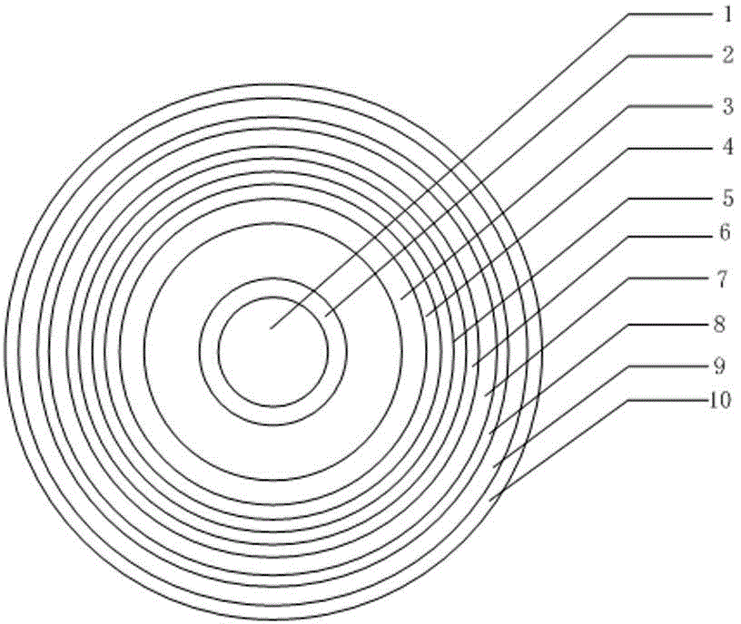
[0020] Such as figure 1 , a power cable provided by the present invention, comprising: a conductor 1 from the inside to the outside, a low-smoke halogen-free flame-retardant wrapping layer 2, a conductor shielding layer 3, an insulating layer 4, an insulating shielding layer 5, and a flame-retardant nitrile inner Sheath layer 6, shielding layer 7, corrugated steel sheath 8, outer sheath 9;

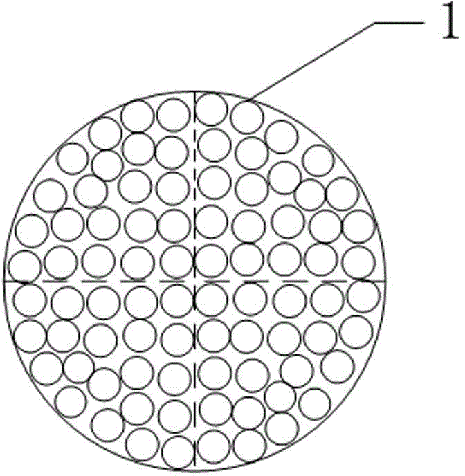
[0021] The cross section of the conductor 1 is a circle or a circle formed by combining multiple fan-shaped conductors. Such as figure 2 As shown, the cross-section of the conductor 1 is a circle formed by combining multiple fan-shaped conductors, which can effectively avoid the skin effect.

[0022] The low-smoke, halogen-free, flame-retardant wrapping layer 2 is made of halogen-free, low-smoke, flame-retardant polyolefin insulation material, which not only improves the flame-retardant ability of the cable, but also reduces the release of toxic fumes during combustion

[0023] In addi...


PUM

PropertyMeasurementUnit
thicknessaaaaaaaaaa
thicknessaaaaaaaaaa
thicknessaaaaaaaaaa

Abstract

A power cable comprises a conductor, a low-smoke halogen-free flame wrapper layer, a conductor shielding layer, an insulating layer, an insulating shielding layer, a butyronitrile flame retardant inner protection sleeve layer, a shielding layer, a corrugated steel protection sleeve and an outer protection sleeve from inside to outside. The cross section of the conductor is round or is a round which is formed by combining multiple sector-shaped conductors. The conductor shielding layer comprises a semi-conduction nylon strip and a conductor shielding material layer, wherein the thickness of the semi-conduction nylon strip is 0.22 mm-0.26 mm, and the thickness of the conductor shielding material layer is 1.3 mm-1.7 mm. The thickness of the insulating layer is 12.0 mm-16.0 mm, and the thickness of the insulating shielding layer is 0.8 mm-1.2 mm. The shielding layer comprises a semiconductor water-blocking strip of which the thickness is 0.8 mm-1.0 mm, a copper wire shield of which the thickness is 2.0 mm-2.4 mm, a sparsely-wound copper strip of which the thickness is 0.1 mm-0.14 mm and a semi-conduction buffering water-blocking strip of which the thickness is 2.5 mm-3.0 mm.

Description

technical field [0001] The invention relates to a basic electrical component, in particular to a power cable. Background technique [0002] At present, ordinary extra-high voltage cables often use lead alloy as the metal sheath layer of the cable, and polyvinyl chloride as the outer sheath layer of the cable. This kind of cable has the following disadvantages: 1. Low mechanical strength, small withstand pressure, and small allowable fault short-circuit current. If the lead sheath is used as the metal sheath, the processing technology is complicated, the environment is polluted, it is not conducive to environmental protection, and it is very heavy. The cost is high, which is not conducive to transportation and laying. If the aluminum sheath is used as the metal sheath and coated with asphalt, the corrosion resistance is poor and the environmental pollution is large. Moreover, most of the current high-voltage cables have poor flame retardancy and often cause safety accidents. ...

Claims


Application Information

Patent Timeline
Patent Type & Authority Applications(China)
IPC IPC(8): H01B9/02H01B7/282H01B7/295H01B7/30H01B7/28
Inventor 刘晓东王志辉郭党庆唐文川崔旭光张景慧
Owner GUANGZHOU NANYANG CABLE
Learn More