
Calcium carbide cooling molding device

A cooling forming, calcium carbide technology, applied in sustainable manufacturing/processing, carbide, chemical industry, etc., can solve problems such as high power consumption, increased calcium carbide cost, long cooling time, etc., to reduce energy loss and reduce calcium carbide powder Or the production of electric lime, the effect of simplifying the production process

Active Publication Date: 2014-10-22
重庆鸿庆达产业有限公司
View PDF10 Cites 5 Cited by
  • Summary
  • Abstract
  • Description
  • Claims
  • Application Information

AI Technical Summary

Problems solved by technology

[0003] Since the calcium carbide pot usually has only one overall cavity, in order to increase the output, the cavity of the calcium carbide pot is often larger, so that the volume of the solidified calcium carbide mound is also larger, which not only makes the cooling time of the calcium carbide longer, but also makes the calcium carbide mound must be Only after crushing can it meet the requirements of calcium carbide finished products
However, during the crushing process of calcium carbide, it is easy to arouse relatively large dust, which will have a certain impact on the environment and staff, and calcium carbide mounds will produce calcium carbide powder or calcium carbide during the crushing process, which will not only cause environmental impacts but also cause resource pollution. At the same time, the operation of the crusher needs to consume more power, and it often needs to change from cooling to crushing. It can be seen that the cooling time is long, the generation of calcium carbide powder or calcium carbide that is difficult to use, more power consumption, more and longer The cost of site occupancy and transit transportation have increased the cost of calcium carbide

Method used


Image

  • Calcium carbide cooling molding device

Examples


Embodiment Construction

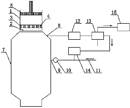
[0022] The present invention provides a kind of calcium carbide cooling molding equipment, see figure 1 , a container 1 with an open upper part is provided, and the container includes a horizontal sieve plate 3 and a cylindrical side wall wrapped around the outside of the sieve plate, and the sieve plate is provided with a number of sieve holes 4 penetrating up and down. The opening of the part of the side wall above the sieve plate is formed as a calcium carbide injection port, the side wall is provided with a hoisting structure and feet, the lower opening of the side wall or the side wall is located on the The bottom of the sieve plate is provided with a movable gate 2 that can be opened and closed, such as a horizontally drawn movable gate. When in use, the calcium carbide that is about to change from a molten state to a solid phase is injected into the container, and the molten calcium carbide temporarily stays on the sieve plate in the container, and after passing throug...


PUM


Abstract

The invention relates to a calcium carbide cooling molding device. The calcium carbide cooling molding device is provided with a cooling tower, an extruding mechanism and a container with an upper opening. The container comprises a horizontal sieve plate and cylindrical side walls wrapping four outer sides of the sieve plate. The sieve plate is provided with several through sieve apertures, and the sieve apertures in the sieve plate close to the four edges have equivalent diameters greater than those of the sieve apertures close to the center of the sieve plate. The extruding mechanism is in a sliding fit relationship with the inner side wall of the container. The top and the bottom of the cooling tower are respectively provided with a calcium carbide feeding inlet and a calcium carbide discharging outlet. The side wall of the cooling tower is provided with an air outlet and an air inlet. A blower is arranged at the air inlet. The top of the cooling tower is provided with a station for receiving the container. The air outlet is connected to a heat release medium inlet of the heat exchanger by a dust remover. The calcium carbide cooling molding device can directly cure small calcium carbide blocks in calcium carbide transformation from a melt state to a solid state, is free of large-block calcium carbide fragmentation, reduces calcium carbide powder or calcium carbide dust produced by calcium carbide fragmentation, and realizes full resource utilization and recovery of heat released in calcium carbide curing.

Description

technical field [0001] The invention relates to a device capable of directly molding calcium carbide into small pieces of calcium carbide during the phase transition process from a molten state to a solid state. Background technique [0002] At present, in the later stage of calcium carbide production, cooling and crushing processes are generally used to obtain finished calcium carbide. The general process is: the smelted calcium carbide is released from the furnace mouth of the calcium carbide furnace once in a while, and the molten calcium carbide flows into the calcium carbide pot on the traction trolley, and the trolley is pulled. Send the calcium carbide pot to the cooling plant, and lift the calcium carbide pot spreader from the traction trolley by the bridge crane, and place it in the "hot pot pre-cooling area". After cooling for several hours, lift the solidified calcium carbide mound from the calcium carbide pot and place it in the cooling zone to continue cooling. ...

Claims


Application Information

Patent Timeline
Patent Type & Authority Applications(China)
IPC IPC(8): C01B31/32C01B32/942
CPCY02P20/10
Inventor 顾君尧
Owner 重庆鸿庆达产业有限公司
Learn More