
Cold stamping trimming die

A technology for trimming molds and cold stamping, which is applied in the field of cold stamping of molds in the automobile industry to achieve the effects of reducing production cycle and manufacturing cost, simple maintenance and simple structure

Inactive Publication Date: 2014-10-08
DONGFENG HONDA AUTOMOBILE CO LTD
View PDF6 Cites 5 Cited by
  • Summary
  • Abstract
  • Description
  • Claims
  • Application Information

AI Technical Summary

Problems solved by technology

[0004] The purpose of the present invention is to address the defects of the prior art, to provide a cold stamping trimming die, to eliminate the surface quality problems of the parts caused by the secondary shearing of the existing stamping trimming die and to improve the efficiency of the production line

Method used


Image

  • Cold stamping trimming die
  • Cold stamping trimming die
  • Cold stamping trimming die

Examples


Embodiment Construction

[0026] The present invention will be further described in detail below in conjunction with the accompanying drawings and specific embodiments to facilitate a clear understanding of the present invention, but they do not limit the present invention.

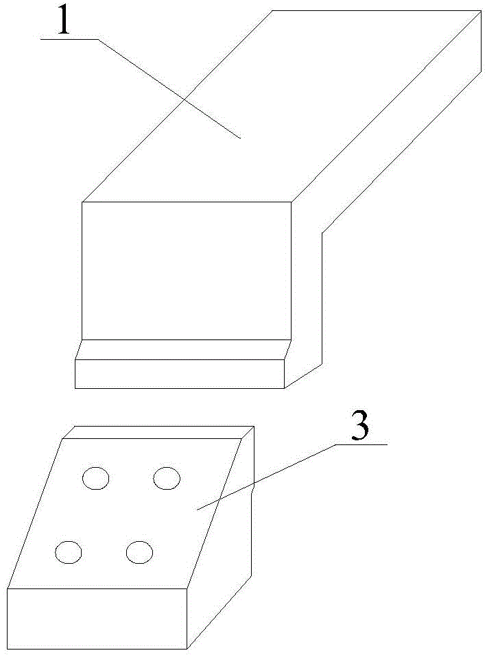
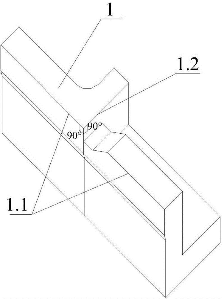
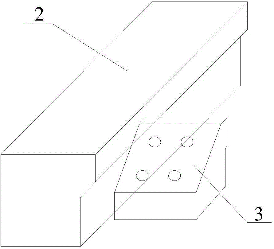
[0027] Such as Figure 4 — Figure 6 As shown, the present invention comprises an upper die block 1, a punch block 2 and a lower die waste block 3, and the lower die waste block 3 is arranged on the side of the punch block 2 lower than the punch block 2 , the upper mold cutter block 1 is arranged above the lower mold scrap cutter block 3, the upper mold cutter block 1 is provided with an upper mold trimming edge 1.1 and an upper mold scrap edge 1.2 that are not on the same straight line, and the upper mold cutter block 1 The trimming edge 1.1 of the mold and the waste material edge 1.2 of the upper mold respectively have a trimming inclined edge 1.11 protruding from the edge trimming edge 1.1 of the upper mold and a waste incline...


PUM


Abstract

The invention relates to a cold stamping trimming die, and belongs to the technical field of cold stamping machining of dies in the automobile industry. The cold stamping trimming die comprises an upper die cutter block, a male die cutter block and a lower die waste cutter block, wherein the lower die waste cutter block is arranged on the part, lower than the male die cutter block, of the side edge of the male die cutter block; the upper die cutter block is arranged above the lower die waste cutter block; an upper die trimming cutting edge and an upper die waste cutting edge are arranged on the upper die cutter block, and are not positioned on the same straight line; the upper die trimming cutting edge and the upper die waste cutting edge are provided with an inclined trimming blade raised from the upper die trimming cutting edge and an inclined waste blade raised from the upper die waste cutting edge at a joint respectively; the inclined trimming blade and the inclined waste blade form a tapered point raised from the upper die trimming cutting edge and the upper die waste cutting edge. According to the cold stamping trimming die, the problem of cutting powder produced by secondary shearing in the prior art is solved, part surface quality problems caused by the cutting powder are solved, and the production efficiency of an automatic line is further improved.

Description

technical field [0001] The invention belongs to the technical field of cold stamping processing of molds in the automobile industry, and in particular relates to a cold stamping trimming mold. Background technique [0002] Existing punching and trimming dies mainly include upper die cutter block, punch die cutter block, binder plate and lower die waste cutter block. Such as figure 1 , figure 2 As shown, the direction of the waste edge of the existing upper die block and the trimming edge are at a 90° angle in the horizontal direction, and the angle between the edge on both sides of the angle and the stamping direction is 90°, forming a double 90° knife tip. Such as image 3 As shown, the height of the cutting edge of the waste knife block of the lower mold is 5mm lower than that of the knife block of the punch mold, and the installation position of the waste knife block of the lower mold is that there is no gap between the tip of the knife and the knife block of the punc...

Claims


Application Information

Patent Timeline
Patent Type & Authority Applications(China)
IPC IPC(8): B21D28/14
Inventor 潘建新申林葛勇
Owner DONGFENG HONDA AUTOMOBILE CO LTD
Learn More