Non-contact type instantaneous rotating speed sensing method
A technology of instantaneous speed and sensing method, which is applied in the field of non-contact instantaneous speed sensing, mechanical quantity, geometric quantity and fluid physical quantity measurement, which can solve eccentricity or relative movement, difficult to eliminate the influence of eccentricity, poor environmental adaptability, etc. problems, to achieve the effect of improving measurement resolution, reducing measurement error sources, and optimizing the sensing structure
- Summary
- Abstract
- Description
- Claims
- Application Information
AI Technical Summary
Problems solved by technology
Method used
Image

Examples
Embodiment 1
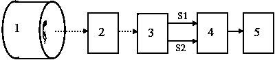
[0043] Embodiment one: see figure 1 , figure 2 , image 3 , the non-contact instantaneous speed sensing method of the present invention, the specific steps are:
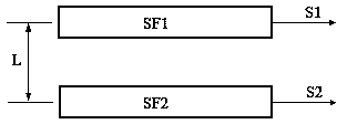
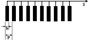
[0044] (1) Use an incandescent light source with a wavelength of 360nm~760nm and a certain intensity to irradiate the end face of the mechanical rotation shaft 1, or use a laser or light-emitting diode (LED) light source with a certain intensity to irradiate the end face of the mechanical rotation shaft 1, or When the natural light intensity is large enough, use a natural light source to irradiate the end face of the mechanical rotating shaft 1; the light illuminates the end face of the mechanical rotating shaft 1 and generates a reflected image, and the random image of the end face of the mechanical rotating shaft 1 is imaged to the optical spatial filter through the optical imaging system 2 pair 3; the optical spatial filter pair 3 is composed of two spatial filters (SF1 and SF2) with the same pitch and structu...
Embodiment 2
[0051] Embodiment 2: Step (1) of Embodiment 2 is the same as (1) in Embodiment 1; (2) is the same as (2) in Embodiment 1; (3) is different from (3) in Embodiment 1 Yes: the two sets of quasi-sine signals (S1 and S2) output by the optical spatial filter pair 3 are directly transmitted to the data acquisition and processing system 5; the data acquisition and processing system 5 uses the center frequency extraction method to obtain two sets of quasi-sine signals (S1 and S2 ) center frequency, and record the center frequencies f1 and f2 of these two groups of quasi-sine signals; the method of extracting the center frequency is: the optical spatial filter performs modulus (A / D) Conversion and data acquisition, or add the two sets of quasi-sine signals output by the optical spatial filter and then perform analog-to-digital (A / D) conversion and data acquisition; then use fast Fourier transform (FFT) Calculate the amplitude spectrum of the collected data to obtain the amplitude spect...
Embodiment 3
[0052] Embodiment 3: Step (1) of Embodiment 3 is the same as (1) in Embodiment 1; (2) is the same as (2) in Embodiment 1; (3) is the same as ( 3) the same; (4) The data acquisition and processing system 5 uses the rotation center positioning method to determine the position of the rotation center imaging point of the measured mechanical rotation axis 1 on the optical spatial filter pair 3, which is different from (4) in the first embodiment The point is: the rotation center positioning method refers to using the center frequency extraction method to obtain the center frequencies of the two quasi-sine signals (S1 and S2) output by the optical spatial filter pair 3 when the rotating object 1 rotates relatively stably After (f1, f2), the optical spatial filter pair 3 is translated for a distance along the radial direction of the measured rotating object 1. This translation distance ensures that the random image of the end face of the measured rotating body can be imaged into the o...
PUM
 Abstract
Description
Claims
Application Information
 - R&D
- Intellectual Property
- Life Sciences
- Materials
- Tech Scout
- Unparalleled Data Quality
- Higher Quality Content
- 60% Fewer Hallucinations
Browse by: Latest US Patents, China's latest patents, Technical Efficacy Thesaurus, Application Domain, Technology Topic, Popular Technical Reports.
© 2025 PatSnap. All rights reserved.Legal|Privacy policy|Modern Slavery Act Transparency Statement|Sitemap|About US| Contact US: help@patsnap.com