Load Cells in High Pressure Hydrogen Environment
A load sensor and sensor technology, applied in instruments, measuring devices, electric/magnetic solid deformation measurement, etc., can solve the problem of not having the ability to detect the safety of high-pressure hydrogen systems, lack of high-pressure hydrogen system materials/machine durability testing equipment and Technology and other issues to achieve the effect of reducing zero drift and creep, ensuring accuracy and stability
- Summary
- Abstract
- Description
- Claims
- Application Information
AI Technical Summary
Problems solved by technology
Method used
Image
Examples
Embodiment 1
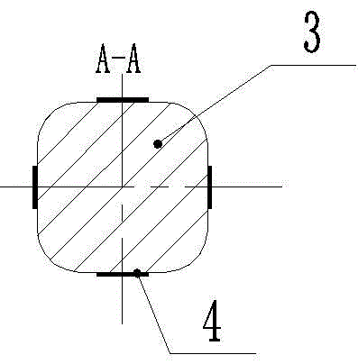
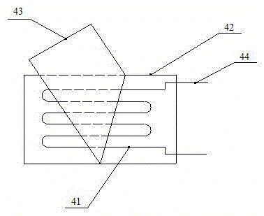
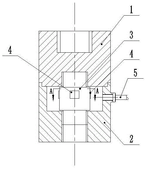
[0028] A load sensor in a high-pressure hydrogen environment (such as figure 1 , 2 shown), including the upper sensor case 1, the lower sensor case 2 and the elastic body 3, the elastic body 3 is threadedly connected with the upper sensor case 1 and the lower sensor case 2 respectively, and the middle part of the elastic body 3 is evenly distributed with foil strain gauges 4, elastic There is a piece of foil strain gauge 4 in the middle of each of the four surfaces of the middle part of the body 3, and the foil strain gauges 4 on the front and rear surfaces of the middle part of the elastic body 3 are arranged laterally (refer to the attached image 3 ), the foil strain gauges 4 on the left and right surfaces in the middle of the elastic body 3 are arranged longitudinally, the foil strain gauges 4 are bonded to the elastic body 3, and the foil strain gauges 4 include a sensitive grid 41 and a base 42 (conventional glass Fiber cloth), covering layer 43 (conventional polytetraf...
Embodiment 2
[0033] The difference between this embodiment and Embodiment 1 is that the thickness of the sensitive grid is 15 μm, and the composition of each element of the iron-based alloy in terms of mass percentage is: 20% chromium, 3% nickel, 1% aluminum, and 76% iron; The thickness of the transition layer is 100nm, and the thickness of the aluminum thin layer is 100nm.
[0034] The thickness of the aluminum oxide protective layer is 10nm, and the processing parameters of the plasma oxidation technology are: the frequency of the radio frequency source used is 15MHz, and the power of the radio frequency source is 2W / cm2 , the gas source is a mixed gas mixed with argon and oxygen at a volume ratio of 10:1, the gas flow rate is 49 sccm, and the reaction chamber pressure is 8×10 4 Pa, the sensitive gate temperature is controlled at 250°C, and the oxidation time is 2.5h.
[0035] Others are with embodiment 1.
Embodiment 3
[0037] The difference between this embodiment and Embodiment 1 is that the thickness of the sensitive grid is 8 μm, and the composition of each element of the iron-based alloy in terms of mass percentage is: 15% chromium, 5% nickel, 3% aluminum, and 77% iron; The thickness of the transition layer is 50nm, and the thickness of the aluminum thin layer is 50nm.
[0038] The thickness of the aluminum oxide protective layer is 5nm, and the processing parameters of the plasma oxidation technology are: the frequency of the radio frequency source used is 12MHz, and the power of the radio frequency source is 2W / cm 2 , the gas source is a mixed gas mixed with argon and oxygen at a volume ratio of 7:1, the gas flow rate is 49 sccm, and the reaction chamber pressure is 5×10 4 Pa, the sensitive gate temperature is controlled at 250°C, and the oxidation time is 1.5h.
[0039] Others are with embodiment 1.
[0040] The load sensor of the present invention has a zero drift of ≤100 μm / m and ...
PUM
| Property | Measurement | Unit |
|---|---|---|
| thickness | aaaaa | aaaaa |
| thickness | aaaaa | aaaaa |
| thickness | aaaaa | aaaaa |
Abstract
Description
Claims
Application Information
 - R&D
- Intellectual Property
- Life Sciences
- Materials
- Tech Scout
- Unparalleled Data Quality
- Higher Quality Content
- 60% Fewer Hallucinations
Browse by: Latest US Patents, China's latest patents, Technical Efficacy Thesaurus, Application Domain, Technology Topic, Popular Technical Reports.
© 2025 PatSnap. All rights reserved.Legal|Privacy policy|Modern Slavery Act Transparency Statement|Sitemap|About US| Contact US: help@patsnap.com


