
Combustion-supporting method of rotary cement kiln burner oxygen enrichment device

A cement rotary kiln and burner technology, which is applied in the direction of combustion method, combustion equipment, non-flammable liquid/gas transportation, etc., can solve the problems of inexhaustible burning of coal in aggravated calciner, reduction of air volume of burner, and environmental protection emission, etc. , to achieve the effect of increasing the temperature field level in the furnace, reducing NOx emissions, and reducing the ignition point of coal combustion

Active Publication Date: 2014-09-17
河南嘉和节能科技有限公司
View PDF8 Cites 5 Cited by
  • Summary
  • Abstract
  • Description
  • Claims
  • Application Information

AI Technical Summary

Problems solved by technology

[0003] The present invention solves the high energy consumption caused by the incomplete combustion of coal in the burner of the cement rotary kiln, which cannot be discharged in an environmentally friendly way; the inferior coal with a low combustion rate will aggravate the inexhaustible combustion of the coal in the calciner and increase the coal consumption. The discharge of exhaust gas also increases; through reasonable design, a combustion-supporting method for the oxygen-enriched device of the cement rotary kiln burner is provided to provide oxygen-enriched combustion for the pulverized coal in the cement decomposition furnace, and the pulverized coal burner coal in the cement kiln The combustion of pulverized coal has a more sufficient amount of oxygen, which increases the combustion rate of pulverized coal, reduces the ignition point of pulverized coal, reduces the air volume of the burner, the temperature field in the furnace increases the flame temperature, and the fuel burns more completely; the coal saving rate reaches 10. %; the kiln tail burner of cement kiln burns pulverized coal in an oxygen-enriched atmosphere, the content of CO in the flue gas decreases, and the content of NO_x decreases with the degree of oxygen enrichment; the emission of NO_x is reduced, and the coal saving rate reaches 15%. left and right to ensure the normal operation of the cement kiln

Method used


Image

  • Combustion-supporting method of rotary cement kiln burner oxygen enrichment device
  • Combustion-supporting method of rotary cement kiln burner oxygen enrichment device

Examples


Embodiment 1

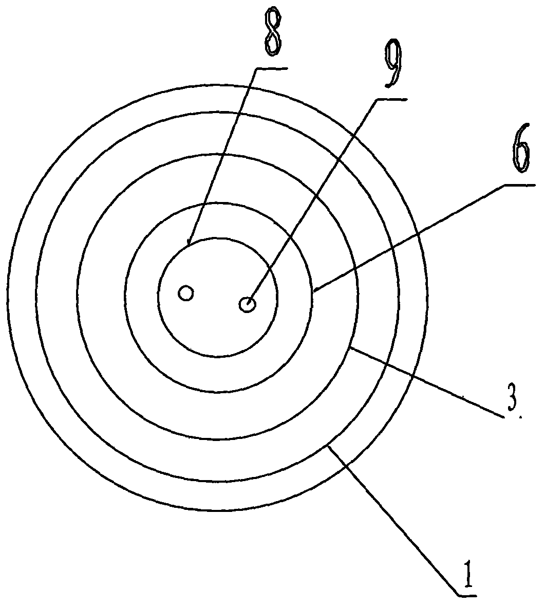
[0020] As shown in the figure; an oxygen-enriching device for a cement rotary kiln burner consists of an outer pipe 1 at the kiln head, an air inlet pipe 2 at the outer layer of the kiln head, a coal bed flow pipe 3 at the kiln head, and a pulverized coal air flow pipe 4 at the kiln head , kiln head coal air duct 5, kiln head internal air duct 6, kiln head internal air inlet pipe 7, kiln head oil pipeline 8, fuel injection nozzle 9, kiln head refractory concrete 10, kiln head oxygen-enriched air duct 11 The rotary kiln burner is provided with four pipes, and the pipe-in-pipe is coaxially arranged: the kiln head oil pipe 8 is provided with the kiln head internal air pipe 6, and the kiln head internal air pipe 6 is provided with the kiln head coal bed flow pipe 3 and the kiln head coal bed flow pipe 6. The outer circumference of the pipeline 3 is provided with the kiln head outer layer pipeline 1, and the outer circumference of the kiln head outer layer pipeline 1 is set with the...

Embodiment 2

[0022] An oxygen-enriched air channel 11 is set between the air inlet pipe opening 2 of the outer layer of the kiln head and the inner air inlet pipe port 7 of the kiln head. Oxygen-enriched air intake.

Embodiment 3

[0024]The enriched oxygen with a concentration of 23% to 50% passes through the air inlet of the kiln head oxygen-enriched air channel 11 in the kiln head inner air inlet pipe 7, and the enriched oxygen enters the kiln head outer layer air intake pipe through the kiln head oxygen-enriched air channel 11 Port 2, enter the kiln head internal air duct 6 through the kiln head outer air inlet pipe port 2, and the oxygen-enriched kiln head enters the cement rotary kiln from the outlet of the kiln head internal air duct 6; at the same time, the air flow of coal powder passes through the kiln head coal powder air flow pipe 4 Input coal powder into the cement decomposition furnace; the oxygen-enriched internal air flow with a concentration of 23% to 50% in the kiln head internal air duct 6 is fully mixed with the pulverized coal air flow at the outlet, and the oxygen-enriched internal air flow is mixed with the pulverized coal air flow to enter the cement In the calciner; at the same ti...


PUM


Abstract

The invention discloses a combustion-supporting method of a rotary cement kiln burner oxygen enrichment device. The rotary cement kiln burner oxygen enrichment device consists of a kiln head outer layer pipeline, a kiln head outer layer air inlet pipe orifice, a kiln head coal layer current pipeline, a kiln head pulverized coal wind current pipeline, a kiln head coal wind pipeline, a kiln head inner wind pipeline, a kiln head inner wind air inlet pipe orifice, a kiln head oil pipeline, an oil nozzle, kiln head refractory concrete and a kiln head oxygen enrichment air flue, wherein the oxygen enrichment air flue is arranged between the kiln head outer layer air inlet pipe orifice and the kiln head inner wind air inlet pipe orifice; an air inlet of oxygen enrichment is preserved in the pipe end of the kiln head oxygen enrichment air flue in the kiln head outer layer air inlet pipe orifice; when the oxygen enrichment in the kiln head outer layer pipeline and the oxygen enrichment in the kiln head inner wind pipeline enter a rotary cement kiln together with pulverized coal wind current simultaneously, the temperature of a combustion field of the rotary cement kiln input with the oxygen enrichment can reach over 1700 DEG C, before free carbon in the combustion field with the temperature of over 1700 DEG C forms black smoke, the free carbon is thoroughly burned, and the free carbon becomes combustive fuel; meanwhile, the clinker catalyst of cement is subjected to oxidation combustion by the input of the oxygen enrichment; when the temperature of the combustion field is over 1700 DEG C, CO in the combustion field is burned, and the emission of NOx is reduced by 35%.

Description

technical field [0001] The invention relates to a coal-fired burner device for a cement kiln, in particular to a combustion-supporting method for an oxygen-enriched burner device for a cement rotary kiln. Background technique [0002] The three-channel and multi-channel calciner burners use the jet flow method composed of direct current and swirl flow to strengthen the pulverized coal combustion process. The swirling flow of the internal wind can cause internal backflow in the center, so as to entrain high-temperature smoke. In the initial stage, the rotating jet has high turbulence intensity, strong mixing, and rapid momentum and heat transfer. Coal and wind are transported at high pressure, with high concentration of pulverized coal, low flow velocity, and small air volume. In this way, the heat required for ignition is relatively small, so it has good ignition performance; the external air adopts DC wind, and the early turbulence intensity of DC jet flow It is not very ...

Claims


Application Information

Patent Timeline
Patent Type & Authority Applications(China)
IPC IPC(8): F27B7/34F23C7/00F23L7/00
CPCY02E20/34
Inventor 葛中伟王政伟朱洪涛
Owner 河南嘉和节能科技有限公司
Learn More