
High-voltage input auxiliary power circuit

A high-voltage input, auxiliary power supply technology, applied in the direction of converting DC power input to DC power output, electrical components, adjusting electrical variables, etc., can solve the problems of high voltage output and low cost.

Inactive Publication Date: 2014-09-10
ZHEJIANG HAIDE NEW ENERGY +1
View PDF4 Cites 8 Cited by
  • Summary
  • Abstract
  • Description
  • Claims
  • Application Information

AI Technical Summary

Problems solved by technology

[0006] The technical problem to be solved by the present invention is to provide a combination circuit of switching tubes, which can meet the requirements of high input voltage and realize low-cost

Method used


Image

  • High-voltage input auxiliary power circuit
  • High-voltage input auxiliary power circuit
  • High-voltage input auxiliary power circuit

Examples


Embodiment Construction

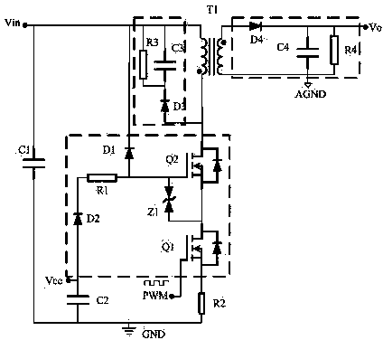
[0015] Such as figure 1 As shown, the patent of the present invention relates to an auxiliary power supply circuit that takes power from the DC side of the inverter. circuit, at least one secondary circuit (including a power supply winding), and the switching tube combination circuit is respectively connected with a DC input circuit, a flyback transformer, a control circuit, a power supply circuit, and a detection circuit.

[0016] The switching tube combination circuit includes MOS tubes Q1 and Q2, TVS tube Z1, diodes D1 and D2, and a current limiting resistor R1; the gate of the MOS tube Q1 is connected to the PWM control circuit, and the source is connected to one end of the current detection resistor R2 The drain is connected to the source of the MOS transistor Q2; the drain of the MOS transistor Q2 is connected to one end of the flyback transformer T1, and the gate is connected to the drive resistor R1 and the anode of the clamping diode D1; the TVS transistor The anode...


PUM


Abstract

The invention relates to a high-voltage input auxiliary power circuit which comprises a switching tube combinational circuit, a control circuit, a flyback transformer, an absorption circuit, a DC input circuit, a power supply circuit, a current detection circuit and at least one secondary circuit. The switching tube combinational circuit is connected with the DC input circuit, the flyback transformer, the control circuit, the power supply circuit and the detection circuit respectively. The switching tube combinational circuit comprises an MOS transistor Q1, an MOS transistor Q2, a TVS transistor Z1, a diode D1, a diode D2 and a current-limiting resistor R1. The grid electrode of the MOS transistor Q1 is connected with a PWM control circuit, the source electrode of the MOS transistor Q1 is connected with one end of a current detection resistor R2, and the drain electrode of the MOS transistor Q1 is connected with the source electrode of the MOS transistor Q2. The drain electrode of the MOS transistor Q2 is connected with one end of the flyback transformer T1, and the grid electrode of the MOS transistor Q2 is connected with the positive electrode of a driving resistor R1 and the positive electrode of the clamping diode D1. The positive electrode of the TVS transistor Z1 is connected with the source electrode of an NMOS transistor Q1, and the negative electrode of the TVS transistor Z1 is connected with the grid electrode of the MOS transistor Q1. The negative electrode of the clamping diode D1 is connected with one end of a DC input capacitor C1. The positive electrode of the diode D1 is connected with the power supply circuit Vcc, and the negative electrode of the diode D1 is connected with the driving resistor R1. The mode that the MOS transistor Q1 and the MOS transistor Q2 are in series connection is adopted in the switching tube combinational circuit, the turn-off voltage stress of the MOS transistors is lowered, and the high-voltage input auxiliary power circuit is suitable for high input voltage auxiliary power supplies; the TVS transistor Z1 is connected with the driving circuits (R1 and D1) and a clamping circuit D1, the driving circuit of the MOS transistor Q2 is simplified, and cost is lowered.

Description

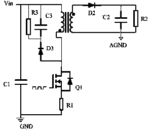
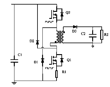
technical field [0001] The invention patent relates to a DC-side high-voltage input auxiliary power supply, which is applied to the fields of wind power converters and photovoltaic inverters. Background technique [0002] Wind power converters and photovoltaic inverters need to meet the technical requirements of low-voltage ride-through of the power grid, that is, to operate uninterruptedly when the grid voltage drops, so the inverter must have an uninterrupted power supply system. The current common solution is to use UPS However, due to the short life of the UPS battery and the narrow operating temperature range (0~40 degrees), the reliability of the inverter power supply system is reduced. Therefore, it is necessary to use an auxiliary power supply that takes power from the DC side of the inverter. [0003] The auxiliary power supply of the inverter is generally multi-channel output, so the flyback auxiliary power supply is usually used in the following two ways: [0004...

Claims


Application Information

Patent Timeline
Patent Type & Authority Applications(China)
IPC IPC(8): H02M3/335
Inventor 吕怀明
Owner ZHEJIANG HAIDE NEW ENERGY
Learn More