
Novel self-circulation greenhouse

A greenhouse and self-circulation technology, which is applied in the field of agricultural greenhouses, can solve problems such as difficulty in maintaining constant temperature, single generation of electric energy or heat energy, and less heat, so as to improve land utilization rate, high energy comprehensive utilization rate, and reduce water consumption. The effect of consumption

Active Publication Date: 2014-09-10
张家港市永联菜篮农业专业合作社
View PDF6 Cites 32 Cited by
  • Summary
  • Abstract
  • Description
  • Claims
  • Application Information

AI Technical Summary

Problems solved by technology

The above-mentioned greenhouses using solar energy are simply combined with solar photovoltaic power generation or photothermal components to generate electricity or heat, and the comprehensive energy utilization efficiency is low.
In addition, most greenhouses can only adjust the room temperature in the greenhouse and cannot adjust the temperature of the soil, especially in winter, the lowest temperature for the normal water absorption and fertilizer absorption of crop roots cannot be reached.
There are also some greenhouses that use heat-absorbing pipes installed underground to form a water cycle to obtain heat. This method obtains less heat, and the supply of temperature in the greenhouse is insufficient, so it is difficult to maintain a certain constant temperature.

Method used

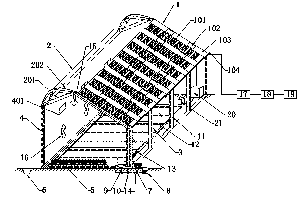
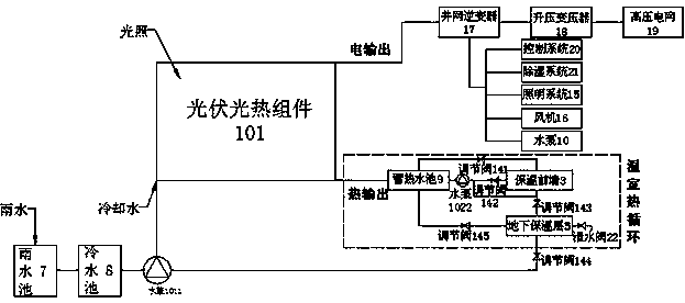
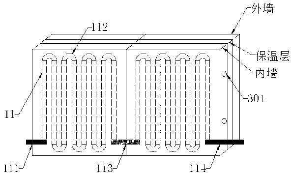

Image

  • Novel self-circulation greenhouse
  • Novel self-circulation greenhouse
  • Novel self-circulation greenhouse

Examples


Embodiment Construction

[0027] The present invention will be further explained below in conjunction with the accompanying drawings and specific embodiments. It should be understood that the following specific embodiments are only used to illustrate the present invention and are not intended to limit the scope of the present invention. It should be noted that the words "front", "rear", "left", "right", "upper" and "lower" used in the following description refer to the direction in the figure, and the words "inner" and "outer ” refer to directions towards or away from the geometric center of a particular part, respectively. The embodiments described below by referring to the figures are exemplary and are intended to explain the present invention and should not be construed as limiting the present invention.

[0028] The novel self-circulating greenhouse greenhouse that the embodiment of the present invention proposes, such as figure 1 As shown, it includes front roof 1, rear roof 2, thermal insulatio...


PUM


Abstract

The invention relates to the technical field of agricultural greenhouses, and discloses a novel self-circulation greenhouse. The novel self-circulation greenhouse mainly comprises a front roof, a rear roof, a heat preservation front wall, a heat preservation rear wall, two side walls, an underground heat preservation layer, a rainwater pond, a cold water pond, a hot water storage pond, heat circulation accessories and a power transmission and energy storage system. The front roof is composed of a photovoltaic photo-thermal assembly and glass fiber reinforced plastic plates. The rear roof comprises a slidable triangular support and a heat preservation quilt, wherein the slidable triangular support is covered with the heat preservation quilt. The cold water pond is arranged behind the rainwater pond and connected with the photovoltaic photo-thermal assembly through a water pump. Hot water which is led out through a photovoltaic photo-thermal assembly water outlet pipe is stored in the hot water storage pond. Rainwater serves as a cooling working medium of the photovoltaic photo-thermal assembly and a heat transfer working medium for greenhouse heat circulation. The hot water storage pond, the heat preservation front wall and the underground heat preservation layer form a greenhouse heat circulation system through connection pieces. The novel self-circulation greenhouse is combined with the photovoltaic photo-thermal technology, the land utilization rate can be increased effectively, heat and electricity are supplied by the novel self-circulation greenhouse, grid-connected power generation can be realized, the comprehensive utilization rate of energy resources is high, and the structure is stable.

Description

technical field [0001] The invention belongs to the technical field of agricultural greenhouses, in particular to a self-supplied greenhouse utilizing solar heat and electricity, in particular to a novel self-circulating greenhouse. Background technique [0002] The energy utilization methods of traditional agricultural greenhouses in my country: one is grid power, and the other is traditional heating methods (including flue heating, hot blast stove heating, steam heating, electric heater heating, etc.). These two methods have adverse effects. In the final analysis, the use of non-renewable fossil energy will not only increase the economic burden of farmers, but will even cause environmental pollution. With the advancement of agricultural modernization, green, environmentally friendly, and energy-saving agricultural production models are becoming more and more respected. Applying solar technology to the control system of greenhouses not only solves some energy problems in g...

Claims


Application Information

Patent Timeline
IPC IPC(8): A01G9/14A01G9/24A01G9/26
CPCY02A40/25Y02P60/12
Inventor 夏彭飞倪建华党艺
Owner 张家港市永联菜篮农业专业合作社
Learn More