Material distributing and defoaming device of evaporator

An evaporator and dispersing device technology, applied in the field of evaporation and separation equipment, can solve problems such as limitations, and achieve the effects of suppressing escape, avoiding foam, and reducing product loss

Inactive Publication Date: 2014-09-03
JIANGSU JIATAI EVAPORATION CRYSTALLIZATION EQUIP
View PDF5 Cites 0 Cited by
  • Summary
  • Abstract
  • Description
  • Claims
  • Application Information

AI Technical Summary

Problems solved by technology

The arc-shaped material box is used to guide the material to spirally decelerate and drop, cut into the material in the shell and then mix with it, avoiding the foam generated by splashing, but limited by the outlet size of the material box, a small amount of liquid foam will still be produced when the flow rate is fast. It has become a bottleneck in improving the processing capacity of evaporation and crystallization equipment, and there is an urgent need for a defoaming device that can effectively suppress liquid splashing at high flow rates

Method used


Image

  • Material distributing and defoaming device of evaporator
  • Material distributing and defoaming device of evaporator
  • Material distributing and defoaming device of evaporator

Examples


Embodiment 1

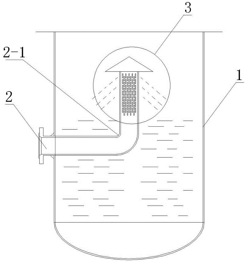
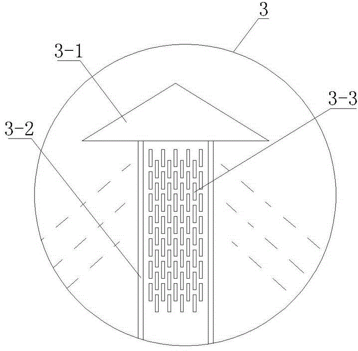
[0017] Embodiment 1: The structure of the evaporator material distribution and defoaming device provided by the present invention is as follows figure 2 and image 3 As shown, it includes a feed pipe 2 pierced on the wall 1 of the evaporator. The feed pipe 2 has an elbow 2-1 on the center line of the evaporator, and the elbow 2-1 is connected with a vertically arranged medium dispersion device. 3 are connected, and the medium dispersing device 3 is fixedly connected by an umbrella-shaped top cover 3-1 and a tubular side wall 3-2, wherein the diameter of the umbrella-shaped top cover 3-1 is 2 times the diameter of the top of the tubular side wall 3-2 times, the rectangular spray holes 3-3 of 4mm*30mm are arranged on the tubular side wall 3-2, wherein the horizontal distance between adjacent spray holes 3-3 in each row of spray holes is equal, and the adjacent two rows of spray holes The shower holes 3-3 are mutually staggered, and the long side of the rectangle is parallel to...

Embodiment 2

[0019] Embodiment 2: The structure of the evaporator material distribution and defoaming device provided by the present invention is as follows Figure 4 and Figure 5 As shown, the structure is basically the same as that of Example 1, the main difference is that the structure of the medium dispersion device 4 is improved, and also includes the feed pipe 2 pierced on the wall 1 of the evaporator, and the center line of the feed pipe 2 in the evaporator There is an upward right-angle elbow 2-1, and the elbow 2-1 communicates with the vertically arranged medium dispersion device 4. The medium dispersion device 4 is fixedly connected by an umbrella-shaped top cover 4-1 and a tubular side wall 4-2. , wherein the diameter of the umbrella-shaped top cover 4-1 is three times the diameter of the top of the tubular side wall 4-2, the tubular side wall 4-2 is in the shape of a circular platform, the height of the circular platform is 600mm, and the included angle between the busbar and ...


PUM

PropertyMeasurementUnit
Heightaaaaaaaaaa

Abstract

The invention discloses a material distributing and defoaming device of an evaporator. The device comprises a feeding pipe arranged on the wall of the evaporator in a penetrating manner, wherein a bend of the feeding pipe is arranged in the evaporator and is communicated with a vertical medium dispersion device; the medium dispersion device comprises a tubular side wall and an umbrella-shaped top cover which are fixedly connected; strip-shaped spraying holes are circumferentially arranged in the tubular side wall in parallel; the horizontal intervals between the adjacent spraying holes in each row of spraying holes are same; the two adjacent rows of spraying holes are staggered from each other; the diameter of the umbrella-shaped top cover is 2-3 times that of the top of the tubular side wall. The device is relatively high in processing capacity and defoaming efficiency.

Description

technical field [0001] The invention relates to an evaporation separation device, in particular to an evaporator material distribution and defoaming device. Background technique [0002] The secondary steam generated by evaporation is usually mixed with solution droplets, especially in the forced circulation evaporator, due to the pressure of the delivery pump, the flow rate of the material entering the separator is fast, and it is easy to impact the equipment, causing the solution to splash and generate foam. , these foams will enter the next effect heat exchanger under the action of negative pressure, and will be discharged after heat exchange and condensation, resulting in the loss of products, especially for the evaporation and crystallization equipment used for sewage treatment, the existence of foams will cause the loss of condensed water COD exceeds the standard and the loss of products. [0003] In order to solve the above problems, the inventor has previously p...

Claims


Application Information

Patent Timeline
IPC IPC(8): B01D1/30
Inventor 树晓荣
Owner JIANGSU JIATAI EVAPORATION CRYSTALLIZATION EQUIP
Why Eureka
Try Eureka