A purging device for removing foreign matter on the surface of an electrostatic chuck

An electrostatic chuck and foreign object technology, which is applied in the direction of cleaning methods, circuits, and electrical components using gas flow, can solve problems such as increasing wafer deformation, vacuum tank pressure alarm, and increasing the process time of purging, so as to avoid Negative pressure alarm problem, convenient operation, and the effect of improving work efficiency

Active Publication Date: 2016-03-16
SHANGHAI HUALI MICROELECTRONICS CORP
View PDF4 Cites 0 Cited by
  • Summary
  • Abstract
  • Description
  • Claims
  • Application Information

AI Technical Summary

Problems solved by technology

[0008] 1) After the pollutants cause the pressure alarm in the vacuum tank, if the reset is invalid, it is necessary to open the cavity for manual cleaning of the electrostatic chuck, which reduces the operating efficiency of the electrostatic chuck;
[0009] 2) Increase the area of ​​the vacuum tank, although it can increase the adsorption force of the negative pressure area on the wafer, but it cannot solve the problem of pressure alarm in the vacuum tank caused by pollutants, and after the area of ​​the vacuum tank increases, the vacuum tank will be enlarged The amount of deformation of the wafer caused by the adsorption of the wafer affects the etching accuracy of the wafer surface;
[0010] 3) Manual purging of the upper surface of the electrostatic chuck can only ensure that the local position of the upper surface of the electrostatic chuck is cleaned, and the pollutants purged from the upper surface of the electrostatic chuck will also be blown onto the electrostatic chuck Other positions on the surface will also cause the alarm problem of the pressure in the vacuum tank;
[0011] 4) Manually purging the upper surface of the electrostatic chuck increases the process time of purging and reduces the operating efficiency of the electrostatic chuck

Method used


Image

  • A purging device for removing foreign matter on the surface of an electrostatic chuck
  • A purging device for removing foreign matter on the surface of an electrostatic chuck
  • A purging device for removing foreign matter on the surface of an electrostatic chuck

Examples


Embodiment

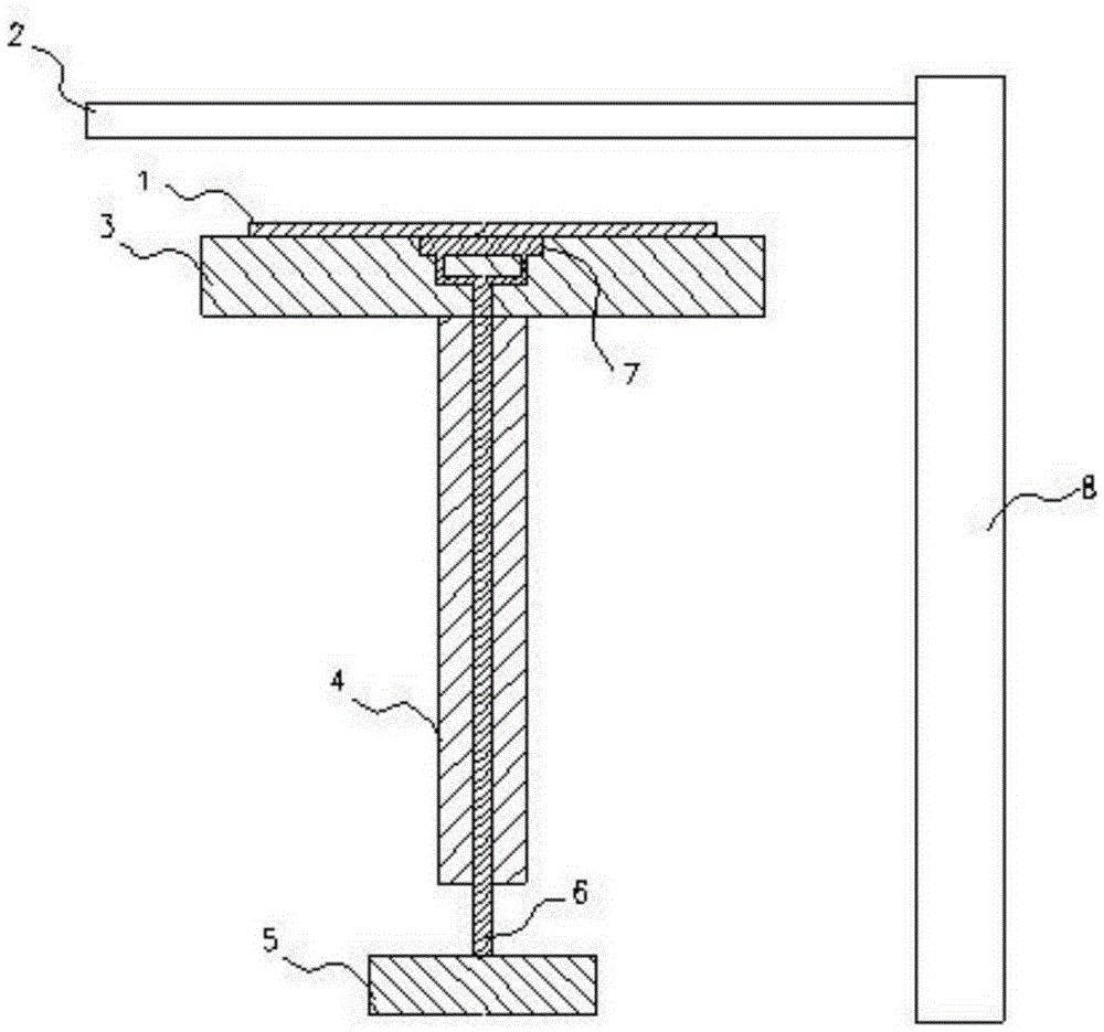
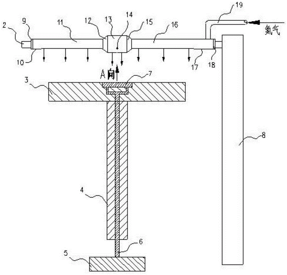
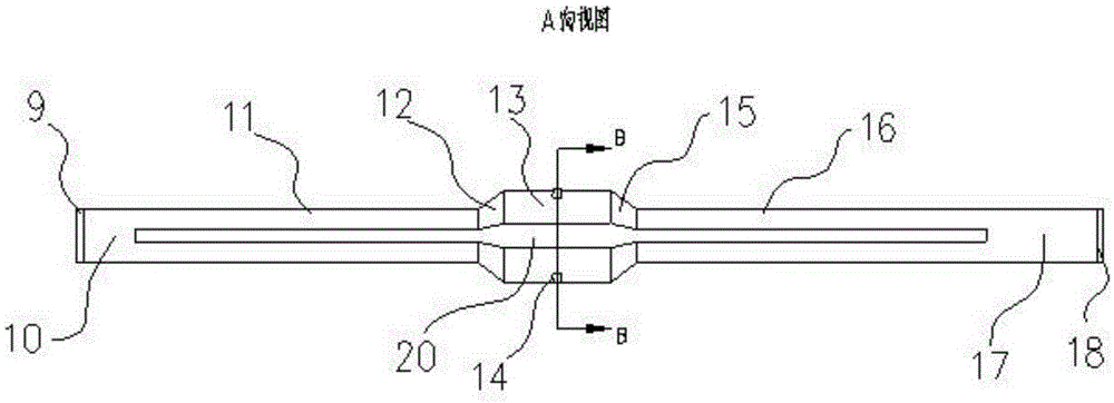
[0039] Such as Figure 2 to Figure 4As shown, a purging device for removing foreign matter on the surface of an electrostatic chuck 3 includes a column 8 arranged vertically to the ground, a cantilever beam 2 arranged horizontally, an electrostatic chuck 3, an electrostatic chuck bracket 4, a negative pressure pump 5, a vacuum Pipeline 6, vacuum tank 7, one end of the cantilever beam 2 is connected to the side of the column 8 near the top; it also includes a middle section nozzle 13, a root nozzle 16, a top nozzle 11, a root blind plate 18 and a top blind plate 9 , the root blind plate 18 and the top blind plate 9 are respectively connected to the outer ends of the root nozzle 16 and the top nozzle 11 in a full welding manner, and the middle section nozzle 13, the root nozzle 16 and the top nozzle 11 are arranged with slotted The opening 20 and the root nozzle 16 are connected with a nitrogen gas inlet pipeline 19 above the side near the column 8, and the nitrogen gas introduc...


PUM


Abstract

A purging device for removing foreign bodies on the surface of an electrostatic chuck comprises a middle-segment spray pipe, a top spray pipe, an opening-degree adjusting bolt, a root spray pipe, a nitrogen gas inlet pipeline and the like. The nitrogen gas inlet pipeline leads nitrogen gas into a seam type opening, and the led nitrogen gas vertically purges the upper surface of the electrostatic chuck; as the diameter of the middle-segment spray pipe is larger than the diameter of the root spray pipe and the diameter of the top spray pipe, the nitrogen gas for purging can establish a pressure gradient on the upper surface of the electrostatic chuck, wherein the pressure at a central point is high, and the pressure on the periphery is low, and therefore it is guaranteed that the pollutants on the upper surface of the electrostatic chuck can be removed completely. The opening-degree adjusting bolt plays a role in adjusting the opening degree of the middle-segment spray pipe, air flow pressure with a larger gradient can be established, and therefore the cleaning degree, at various pollution degrees, of the upper surface of the electrostatic chuck can be guaranteed. In this way, the problem of negative pressure warning of an electrostatic chuck can be avoided, in addition, the purging device is convenient to operate, and the operation efficiency of the electrostatic chuck is enhanced.

Description

technical field [0001] The utility model relates to the technical field of integrated circuit manufacturing, in particular to an electrostatic chuck surface cleaning device for wafer processing. Background technique [0002] At present, various integrated circuit manufacturers widely use an electrostatic chuck device in wafer processing. The electrostatic chuck device is used to absorb and fix the wafer, such as figure 1 As shown, among them, 1 is a wafer, 2 is a cantilever beam, 3 is an electrostatic chuck, 4 is an electrostatic chuck bracket, 5 is a negative pressure pump, 6 is a vacuum pipeline, 7 is a vacuum tank, and 8 is a column; the negative pressure pump passes through The vacuum pipe and the vacuum groove adsorb the wafer on the upper surface of the electrostatic chuck, and the cantilever beam is connected with a mechanical arm for etching the upper surface of the wafer. Because the etching on the surface of the wafer requires a precision of 10 nanometers, it is r...

Claims


Application Information

Patent Timeline
Patent Type & Authority Patents(China)
IPC IPC(8): B08B5/02H01L21/67
CPCB08B5/02H01L21/67017
Inventor 徐春晖邰晓东刘玮
Owner SHANGHAI HUALI MICROELECTRONICS CORP
Why Eureka
Try Eureka