
Groove power device structure and manufacturing method thereof

A power device and manufacturing method technology, applied in the field of trench power device structure and its manufacture, can solve the problems of large environmental impact, large occupied area, premature breakdown at the bottom of the trench, etc., and achieve low cost and high voltage resistance Strong, small terminal size effect

Inactive Publication Date: 2014-07-30
CHANGZHOU WANGTONG SEMICON TECH
View PDF5 Cites 0 Cited by
  • Summary
  • Abstract
  • Description
  • Claims
  • Application Information

AI Technical Summary

Problems solved by technology

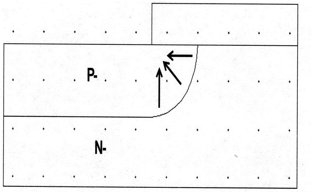
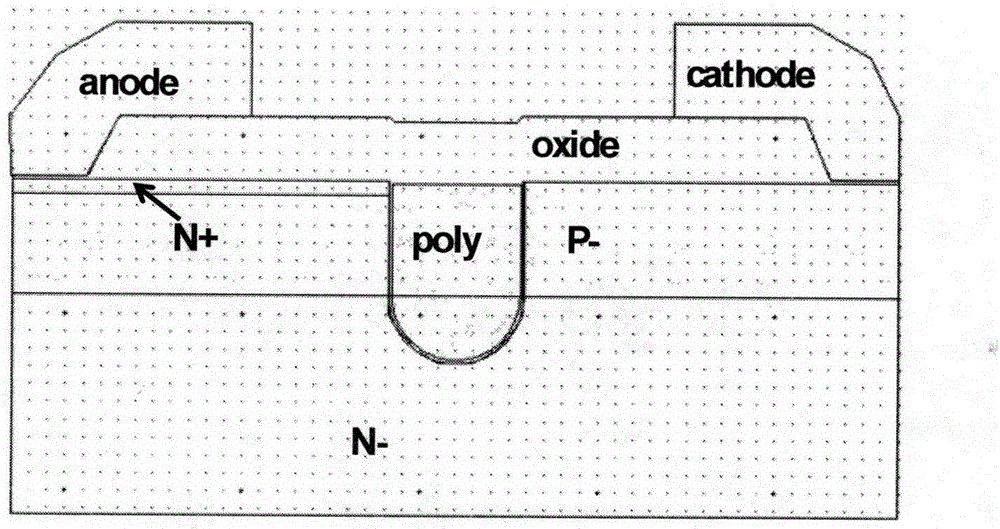
For example, the advantage of the pressure divider ring structure is that the process is relatively simple, but the disadvantage is that it occupies a large area and is greatly affected by the environment, so it needs to be covered with a protective layer; figure 2 The shown trench isolation structure uses the principle that the electric field is terminated on the sidewall of the trench to achieve the purpose of increasing the withstand voltage. This method is feasible for devices below 100V, because the voltage is low, and the depletion layer will not bypass the trench. However, as the voltage increases, the depletion layer also expands downward, and there is a risk of bypassing the trench. In order to solve this risk, the only way to deepen the trench is to bring the bottom of the trench It is easy to break down prematurely, so the problem that the breakdown at the bottom of the trench and the breakdown of the P-N junction cannot be satisfied at the same time, so trench isolation can only be applied to products below 100V

Method used


Image

  • Groove power device structure and manufacturing method thereof
  • Groove power device structure and manufacturing method thereof
  • Groove power device structure and manufacturing method thereof

Examples


Embodiment Construction

[0033] Below in conjunction with accompanying drawing, the patent of the present invention is described in detail.

[0034] In order to make the object, technical solution and advantages of the present invention clearer, the present invention will be further described in detail below in conjunction with the accompanying drawings and embodiments. It should be understood that the specific embodiments described here are only used to explain the present invention, not to limit the present invention.

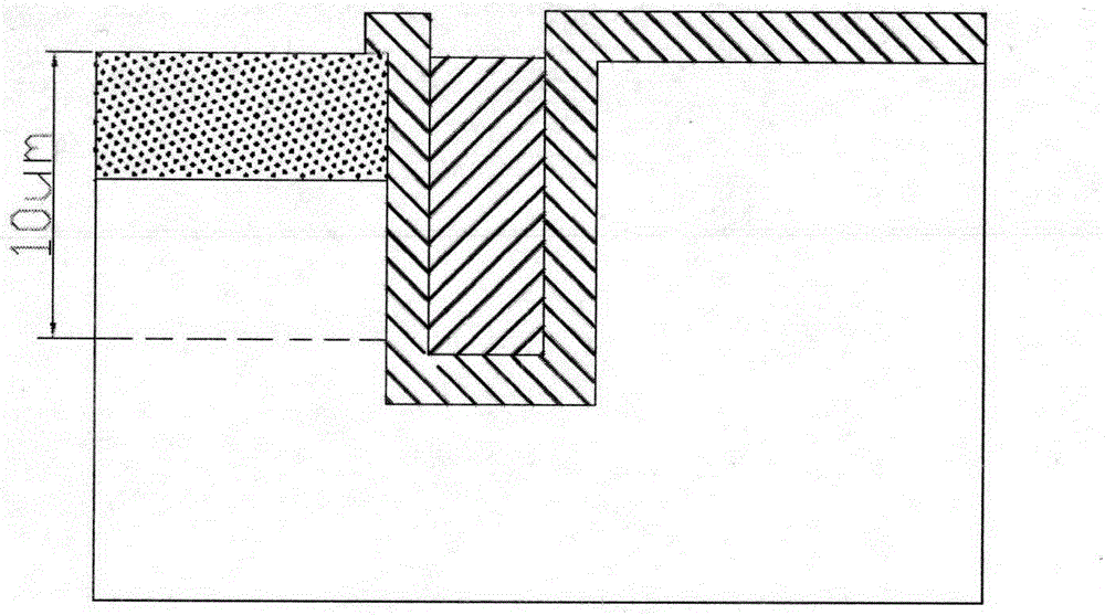
[0035] Such as Figure 5 , Figure 12 As shown, the trench power device of the present invention includes two parts, an active area and a terminal (taking a power device MOSFET as an example), wherein, the outermost circle of trenches in the active area starts until the edge of the device, and the trench is located at the first On the first layer of photoresist, the second layer of photoresist is provided with LOCOS region, the second layer of photoresist is provided with contact h...


PUM


Abstract

The invention discloses a groove power device structure and a manufacturing method thereof. The groove power device structure comprises an active area and a terminal, wherein a groove is formed in a first photolithography mask layer from the outermost periphery of the active area to the edge of the device, an LOCOS area is arranged on a second photolithography mask layer, a contact hole is formed in the second photolithography mask layer, a source electrode and a grid electrode are arranged on a fourth photolithography mask layer, and groove isolation is combined with LOCOS. On the basis of advantages of various terminal structures, the structure is simple in process, low in cost, small in occupied area and wide in voltage application range and the like.

Description

technical field [0001] The invention relates to the technical field of semiconductor devices and manufacturing methods thereof, in particular to a trench power device structure and a manufacturing method thereof. Background technique [0002] At present, Metal Oxide Semiconductor Field Effect Transistor (MOSFET), Insulated Gate Bipolar Transistor (IGBT), Trench Metal Barrier Schottky Diode (TMBS) and Super Barrier Diode (SBD) are some of the most important power device. They are used in various fields of industrial electronics, home appliances and consumer electronics. They are inseparable from switching power supply circuits, rectifier circuits and drive circuits. Power devices require a large forward current and a large reverse voltage. Since the invention of power devices, improving their reverse withstand voltage capability has become an important issue. [0003] The withstand voltage capability of a power device consists of two parts: one is the withstand voltage of...

Claims


Application Information

Patent Timeline
Patent Type & Authority Applications(China)
IPC IPC(8): H01L29/78H01L21/336
CPCH01L27/088H01L21/76202H01L21/76224H01L21/823481
Inventor 孙效中沈志伟吴江郑迎新
Owner CHANGZHOU WANGTONG SEMICON TECH
Learn More