Two-motor driving type cascading multi-level inverter system without active front end and control method thereof

A cascaded multi-level, motor-driven technology, applied in motor generator control, motor/generator/inverter limiter, control system, etc., can solve the adverse effects of increasing the complexity of the control system and system reliability , increase the cost of detection links, etc., to achieve the effect of improving energy utilization efficiency, obvious energy saving effect, avoiding energy feeding and harmonic injection

Active Publication Date: 2014-07-23
WUHAN UNIV
View PDF8 Cites 9 Cited by
  • Summary
  • Abstract
  • Description
  • Claims
  • Application Information

AI Technical Summary

Problems solved by technology

Although it can meet the performance requirements of bidirectional flow of energy, the introduction of PWM rectification circuit requires a phase-shifting transformer with a more complex winding structure, and the cost of the phase-shifting transformer is high, which is not conducive to large-scale industrial application
In addition, the PWM rectifier control circuit needs to detect the amount of information such as the AC side current and the DC side voltage to implement the PWM rectification control algorithm, which not only increases the cost of the detection link, but also increases the complexity of the control system
In addition, the three-phase PWM rectifier circuit (that is, the active front end) is connected to the grid, and while feeding energy back to the grid, it also injects some harmonics into the grid, which has a negative impact on the reliability of the system.

Method used


Image

  • Two-motor driving type cascading multi-level inverter system without active front end and control method thereof
  • Two-motor driving type cascading multi-level inverter system without active front end and control method thereof
  • Two-motor driving type cascading multi-level inverter system without active front end and control method thereof

Examples


Embodiment Construction

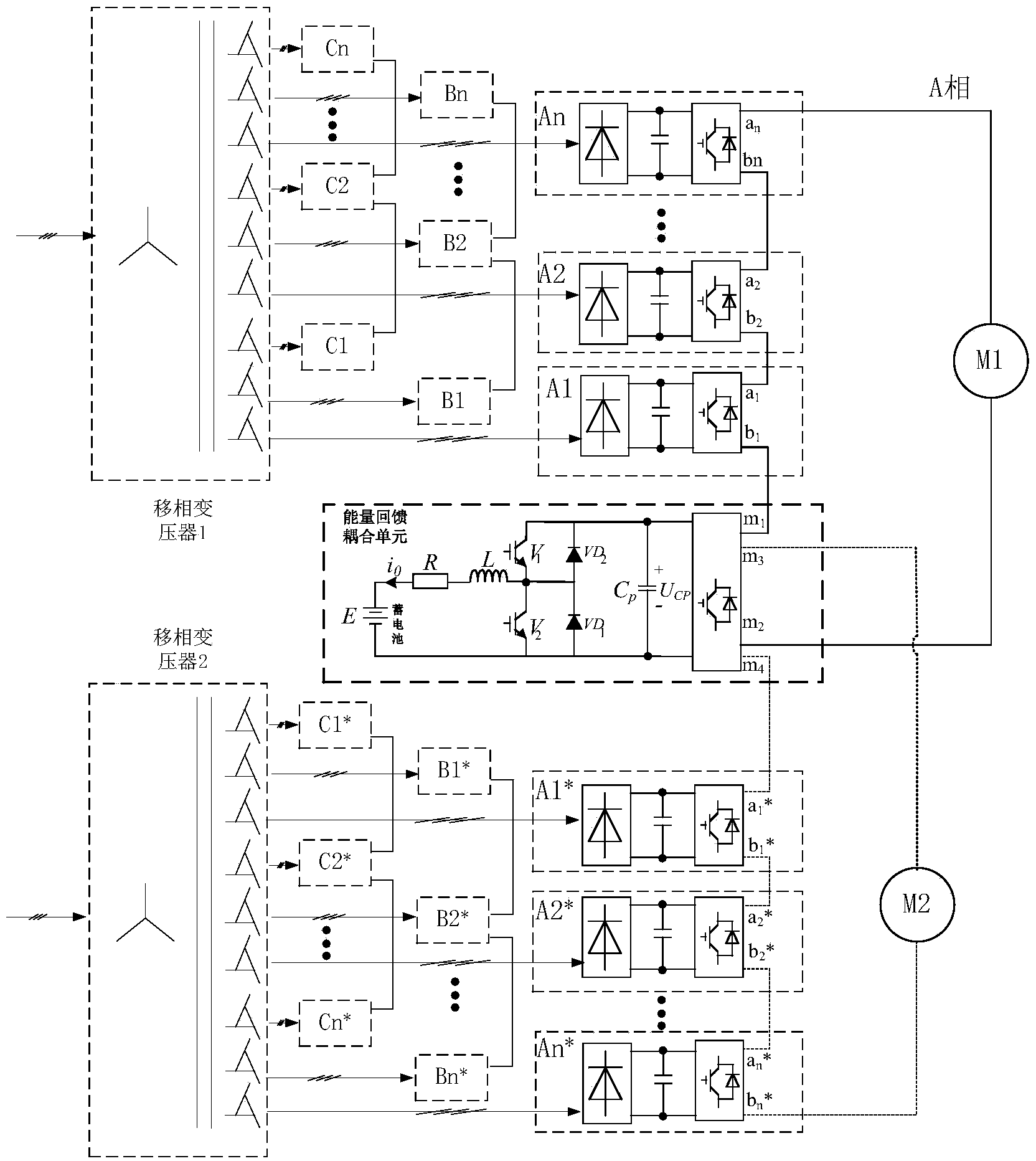
[0030] In order to make the technical solutions and beneficial effects of the present invention more obvious and understandable, the present invention will be further described in detail below in conjunction with the accompanying drawings and specific implementation methods. Wherein, it is assumed that the motor M1 works in a braking state, and the motor M2 works in a motoring state.

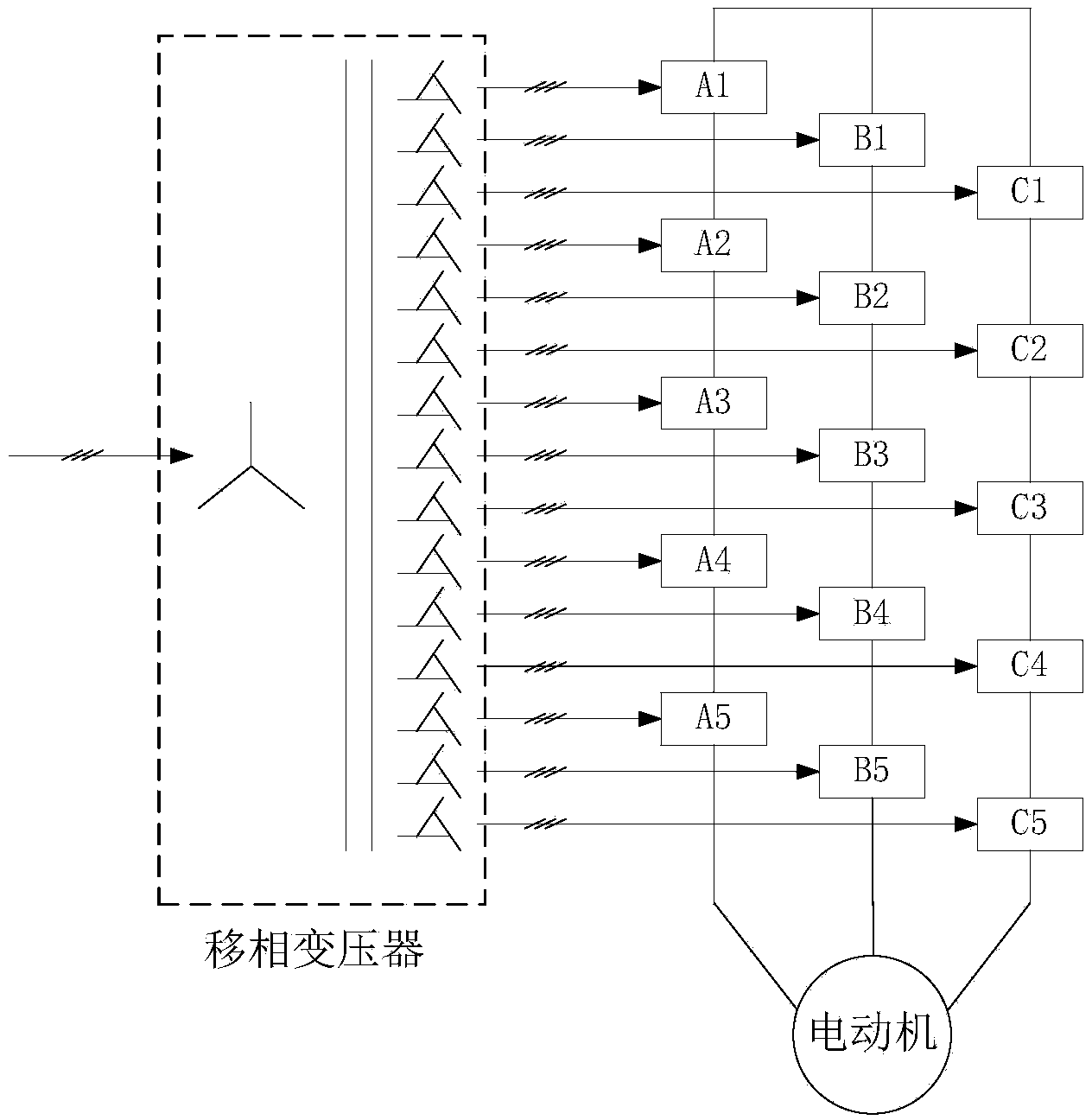
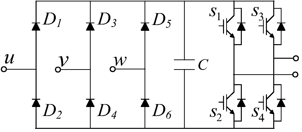
[0031] image 3 For the present invention, two motors drive the cascaded multi-level inverter system, in figure 1 The energy feedback coupling unit is added to the traditional cascaded multilevel inverter shown. See figure 1 , the traditional cascaded multilevel inverter consists of 3n cascaded power units based on three-phase uncontrolled rectifier circuits and H-bridge inverter circuits. The circuit structure of the power units is shown in figure 2 , n power units are cascaded as one phase of the three-phase inverter.

[0032] Figure 4 It is a schematic diagram of the circuit structure ...


PUM


Abstract

The invention discloses a two-motor driving type cascading multi-level inverter system without an active front end and a control method thereof. The system comprises an energy feedback coupling unit arranged between a power unit of a first cascading multi-level inverter and a power unit of a second cascading multi-level inverter, wherein the energy feedback coupling unit comprises a first inverter circuit, a second inverter circuit, a middle direct voltage capacitor, a current reversible chopper circuit, a buffering inductor, a buffering resistor and a storage battery, the current reversible chopper circuit comprises a buck chopper circuit part and a boost chopper circuit part, the switching between the buck chopping mode and the boost chopping mode is achieved according to the voltage between the two ends of the middle direct voltage capacitor, and then energy can be fed back to the storage battery and recycled to drive motors to run. According to the system, a bidirectional transducer based on a three-phase PWM rectifying circuit is not needed, winding remaking of a phase-shifting transformer is avoided, the energy feedback coupling unit does not need to be connected with a power grid, the complexity and cost of the system can be reduced, energy feeding and harmonic wave injection to the power grid are avoided, and the system is suitable for large-scale application.

Description

technical field [0001] The invention belongs to the technical field of power electronics, and in particular relates to a two-motor-driven cascaded multi-level inverter system without an active front end and a control method. Background technique [0002] With the development of power electronics technology, high-voltage inverters, as one of the main achievements of power electronics technology development, have been widely used in production, life, transportation, medical and health due to their high power factor, high efficiency, high precision, and wide speed range. And other fields, to drive the motor to run, and play an increasingly important role. [0003] At present, most of the common high-voltage inverters on the market are cascaded multi-level inverter circuit structures composed of power units based on three-phase uncontrolled rectification circuits. For the circuit topology of traditional cascaded high-voltage inverters, see figure 1 , the circuit topology result...

Claims


Application Information

Patent Timeline
IPC IPC(8): H02M7/797H02P5/74H02P3/18
Inventor 刘飞查晓明邓凯姚俊涛宫金武
Owner WUHAN UNIV
Why Eureka
Try Eureka