
Needle type locating adjustable hydraulic type clamp for machining of tenon of precisely forged blade

A blade mortise and hydraulic technology, which is applied in the field of needle-type positioning adjustable hydraulic fixtures, can solve problems affecting processing quality, safety production, blade quality, and processing accuracy, so as to avoid the impact of blade body quality and benefit Large-scale production and the effect of improving processing efficiency

Inactive Publication Date: 2014-07-23
NORTHWESTERN POLYTECHNICAL UNIV
View PDF7 Cites 36 Cited by
  • Summary
  • Abstract
  • Description
  • Claims
  • Application Information

AI Technical Summary

Problems solved by technology

However, the production preparation of this process is complicated, the working hours are long, the work efficiency is low, and the labor intensity of the workers is too high, which affects the safety of production and the quality of the blades.
Due to the subsequent high-temperature melting process, low-melting-point alloys may also have trace residues on the surface of the blade, which have a certain potential impact on the surface of the blade body, and there is certain pollution in the low-melting-point alloy casting process, and the working conditions are harsh. Greater hidden danger
[0003] The blade body six-point positioning processing method proposed in the invention patent CN102615534A uses clamps to position and clamp the blade body. However, since the blade body is a thin-walled free-form surface structure, clamping the blade body will generate a large stress concentration, which is harmful to the blade body. Deformation of the blade profile affects machining accuracy
Moreover, when processing the mortise, the mortise is divided into a cantilever beam structure, which is prone to vibration and knife-shifting during processing, which seriously affects the processing quality

Method used


Image

  • Needle type locating adjustable hydraulic type clamp for machining of tenon of precisely forged blade
  • Needle type locating adjustable hydraulic type clamp for machining of tenon of precisely forged blade
  • Needle type locating adjustable hydraulic type clamp for machining of tenon of precisely forged blade

Examples


Embodiment Construction

[0023] Now in conjunction with embodiment, accompanying drawing, the present invention will be further described:

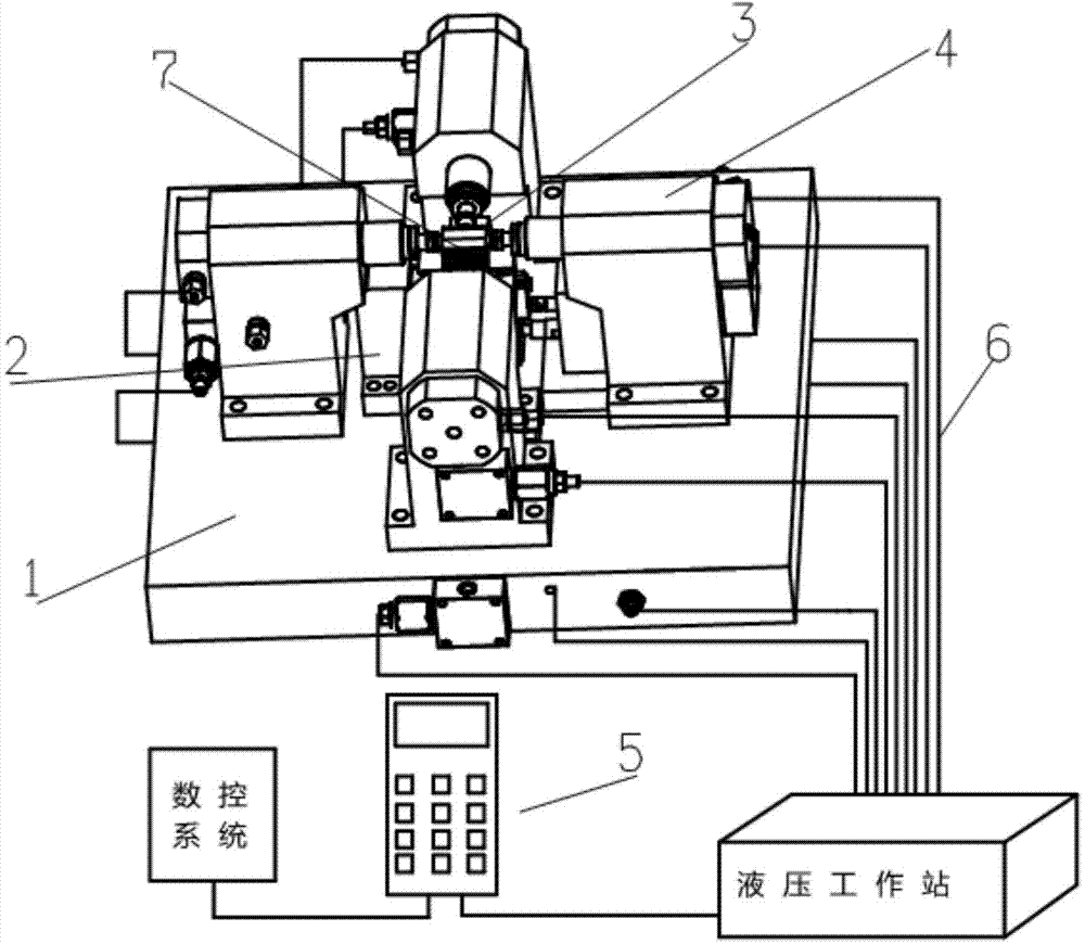
[0024] A needle-type positioning adjustable hydraulic clamp for precision forging blade tenon processing, including a mounting base 1, a positioning device 2, a clamping device 3, an auxiliary support device 4, a main controller 5 and a control circuit 6.

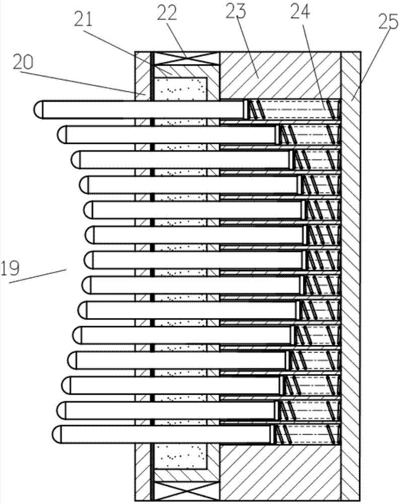
[0025] The positioning device 2 is used for positioning the blade body curved surface of the blade 7, including a thimble matrix positioning part 8, two positioning pins 9 and a positioning block 10, wherein the thimble matrix positioning part 8 is fixed on the installation base 1 and is in contact with the blade body of the blade 7 , the positioning pin 9 is fixed on the installation base 1 and is in contact with the air intake edge of the blade 7 , and the positioning block 10 is fixed on the upper end of the thimble matrix positioning member 8 and is in contact with the inner side of the blade root of the bl...


PUM


Abstract

The invention relates to a needle type locating adjustable hydraulic type clamp for machining of a tenon of a precisely forged blade. The needle type locating adjustable hydraulic type clamp comprises an installation base, a locating device, a clamping device, an auxiliary supporting device, a main controller and a control loop. As a blade body is located and clamped from multiple points, the locating and clamping stability is ensured, self-adaption auxiliary supporting is provided for the tenon, reactive force is provided, cutting deformation is offset, the rigidity of the blade is improved, machining is more stable, and the milling accuracy of the tenon is improved. Influence on the quality of the blade body from a traditional process can be avoided, machining efficiency is improved, and machining cost is lowered. The digital control technology is adopted, the degree of automation is high, operation is easy and convenient, and large-scale production is facilitated.

Description

technical field [0001] The invention relates to the technical field of aero-engine blade processing, and specifically proposes a needle-shaped positioning adjustable hydraulic clamp used for precision numerical control machining of margin-free precision forging blade tenons. Background technique [0002] In the field of aviation industry, the turbofan engine has become the main engine of the current jet aircraft. It has outstanding advantages such as higher strength, bearing capacity, and longer life. The main blades of the engine are mostly thin-walled structures with complex free-form surfaces. The design High precision requirements and high processing difficulty put forward higher requirements for blade processing fixtures. In order to improve the processing efficiency and blade quality, the compressor rotor blades are mainly manufactured by precision forging without allowance. The existing precision forging technology can only meet the accuracy requirements of the blade ...

Claims


Application Information

Patent Timeline
IPC IPC(8): B23Q3/08
CPCB23Q3/063B23Q3/082B23Q2703/04B23Q2703/10
Inventor 黄利江寇萌田锡天
Owner NORTHWESTERN POLYTECHNICAL UNIV
Learn More