
Sludge filtering machine

A filter and sludge technology, applied in the direction of dewatering/drying/concentrating sludge treatment, etc., can solve problems such as difficulty, environmental pollution, and mud overflow, and achieve the effect of reducing filtration cost, high filtration efficiency, and preventing clogging

Active Publication Date: 2014-07-16
KANGTAI JIANGSU ENVIRONMENTAL PROTECTION LTD BY SHARE LTD
View PDF4 Cites 3 Cited by
  • Summary
  • Abstract
  • Description
  • Claims
  • Application Information

AI Technical Summary

Problems solved by technology

[0004] 2) The centrifugal dehydrator is suitable for the concentration and dehydration of various sludges, and the belt filter press is also suitable for various sludges, but a large amount of chemicals are required for the remaining activated sludge and water plant sludge and dehydration is difficult
[0008] 6) The centrifugal dehydrator occupies a small space and is easy to install and debug. The supporting equipment is only the dosing and feeding and discharging conveyors. The whole machine is fully sealed and operates in a good workshop environment. In addition to the feed and discharge conveyors, pumps, air compressors, sludge conditioners, etc. need to be flushed. The sealing of the whole machine is poor, and the high-pressure cleaning water mist and odor will pollute the environment. If the management is not good, the mud will overflow.
However, the wear and tear of the movable and fixed rings in the later stage of this kind of sludge dewatering machine, the cost of replacing the movable and fixed rings is also a large expense

Method used


Image

  • Sludge filtering machine
  • Sludge filtering machine

Examples


Embodiment 1

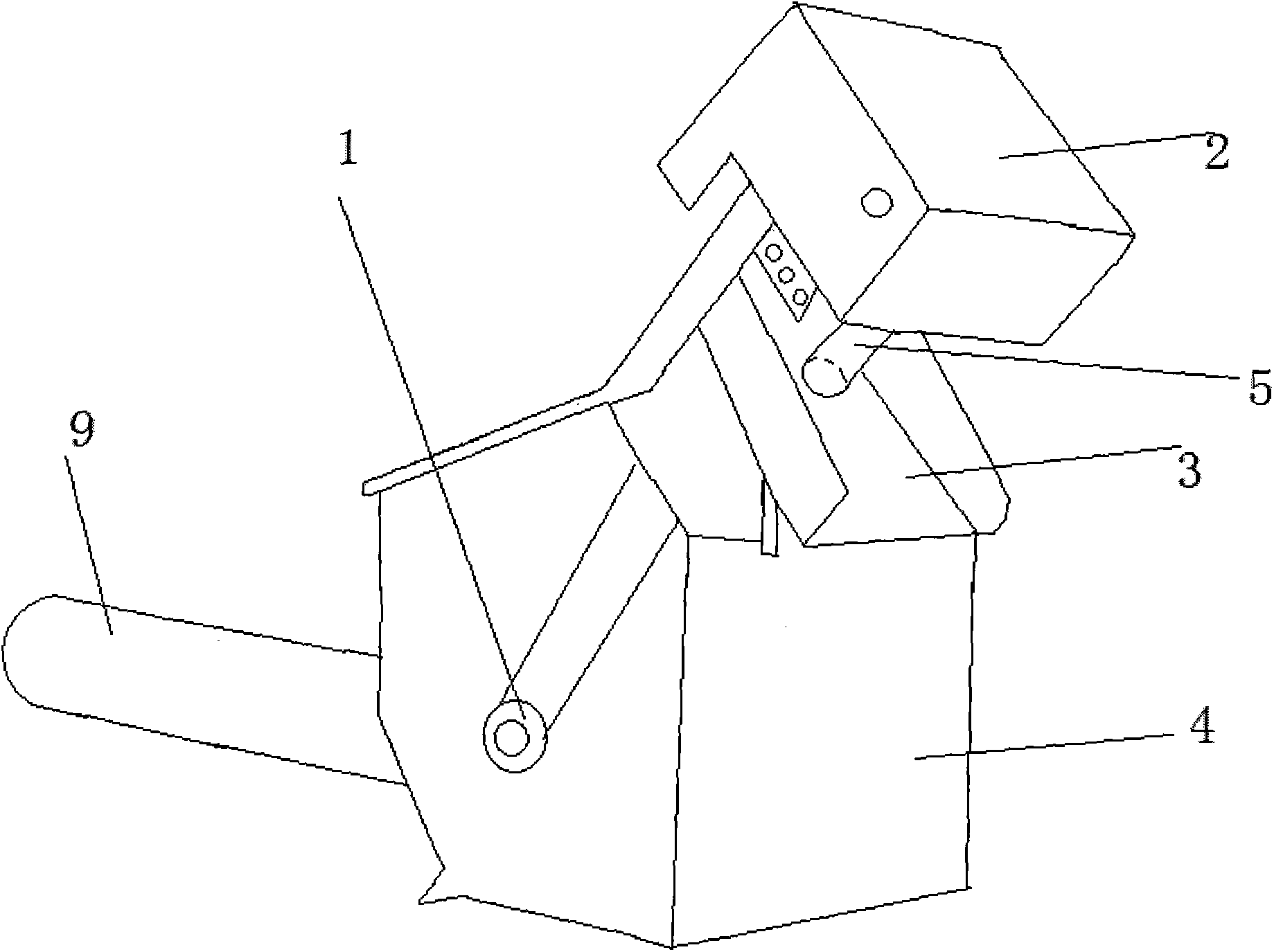
[0021] A sludge filter, such as Figure 1-2 As shown, it includes a drive motor 1, an electric control box 2, a discharge port 3, a housing 4, a drive shaft 5, a cone 6 and a filter shower head 7, the drive motor 1 is arranged in the housing 4, and is connected to the drive shaft 5, The drive shaft 5 is connected with the electric control box 2, the bottom of the electric control box 2 is provided with a discharge port 3, the end of the drive shaft 5 is provided with a cone 6, and the entrance of the cone 6 is connected with the filter shower head 7. Filtration shower head 7 is also connected with pipeline 9.

[0022] The cone 6 is composed of an upper vertebral body 8 and a lower vertebral body 10 , and the upper vertebral body 8 is provided with a helical blade 11 and a blocking ring 12 . The blocking ring 12 blocks the upward movement of the sludge and guides the sludge to flow to the discharge port 3 .

[0023] The filter shower head 7 is made of a stainless steel tube w...


PUM


Abstract

The invention discloses a sludge filtrating machine which is energy-saving, simple in operation and high in deslugding rate and belongs to the technical field of sludge dewatering. The filtering machine is structurally characterized in that a driving motor is arranged in a shell and connected with a driving shaft; the driving shaft is connected with an electric cabinet; the lower part of the electric cabinet is provided with a discharge port; the end part of the driving shaft is provided with a conical body; and the inlet of the conical body is connected with a filtration shower head. According to the sludge filtering machine, the conical body structure is adopted for dewatering and compacting waste materials, so that the volume is reduced, and thus the filtration cost is reduced; the semicircular filtration shower head is adopted, so that the filtration efficiency is high; an Archimedes screw rod is used for transferring the waste materials intercepted by a filtering net to the conical body, and then most moisture of the waste materials is removed by virtue of pressure generated by the conical body; and a special brush at the outer edge of the screw rod is used for thoroughly cleaning holes of a filter and preventing the holes from being blocked.

Description

technical field [0001] The invention belongs to the technical field of sludge dewatering, and in particular relates to a sludge filter with energy saving, simple operation, wear resistance and high sludge removal rate. Background technique [0002] There are mainly 4 kinds of sludge dewatering machines on the existing market: belt filter press, plate and frame filter press, centrifugal dewatering machine and stacked screw sludge dewatering machine. Each of these four sludge dewatering machines has its own advantages and disadvantages. The overall comparison is as follows: [0003] 1) The centrifugal dehydrator uses the principle of centrifugal sedimentation to separate the solid from the liquid. Since there is no filter screen, it will not cause clogging, while the belt filter press uses the filter belt to separate the solid from the liquid. In order to prevent the filter belt from clogging, it needs to be continuously washed by high-pressure water . [0004] 2) The centri...

Claims


Application Information

Patent Timeline
IPC IPC(8): C02F11/12
Inventor 袁浙飞袁飞花成巍
Owner KANGTAI JIANGSU ENVIRONMENTAL PROTECTION LTD BY SHARE LTD
Learn More