
Injection molding machine automatic feeding device

An automatic material feeding and injection molding machine technology, applied in the direction of conveying bulk materials, conveyors, transportation and packaging, etc., can solve the problems of high production cost and maintenance cost, complex structure of automatic material suction machine, obstructed air flow, etc., and achieve simple structure , low maintenance cost and long service life

Active Publication Date: 2016-06-15
宁波禾采医疗器械有限公司
View PDF4 Cites 0 Cited by
  • Summary
  • Abstract
  • Description
  • Claims
  • Application Information

AI Technical Summary

Problems solved by technology

And this type of existing automatic material suction machine often has the following disadvantages: 1) in the situation of continuous work for a long time, the damage of components and parts is prone to affect the continuity of production, 2) the storage in the above-mentioned material storage box is often accompanied by certain For powdery materials, after a certain period of time, a large amount of powdery materials are sucked into the feeding cylinder, which will cause the filter screen in the above-mentioned automatic material suction machine to be clogged, resulting in the obstruction of the air flow, and the excessive load of the vacuum pump, which will eventually lead to the breakdown of components. 3) The structure of the automatic suction machine is complicated, and the production cost and maintenance cost are relatively high

Method used


Image

  • Injection molding machine automatic feeding device
  • Injection molding machine automatic feeding device
  • Injection molding machine automatic feeding device

Examples


Embodiment Construction

[0023] The present invention will be further described below in conjunction with the accompanying drawings and specific embodiments.

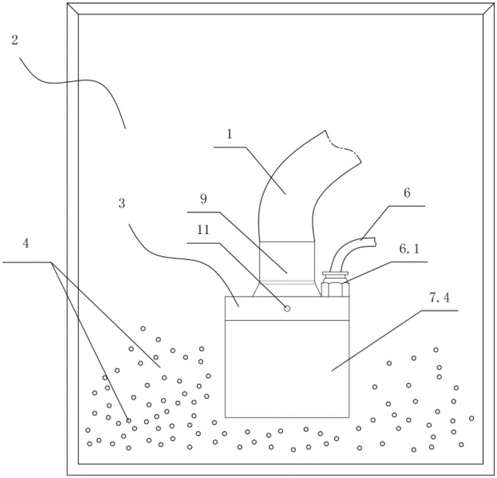
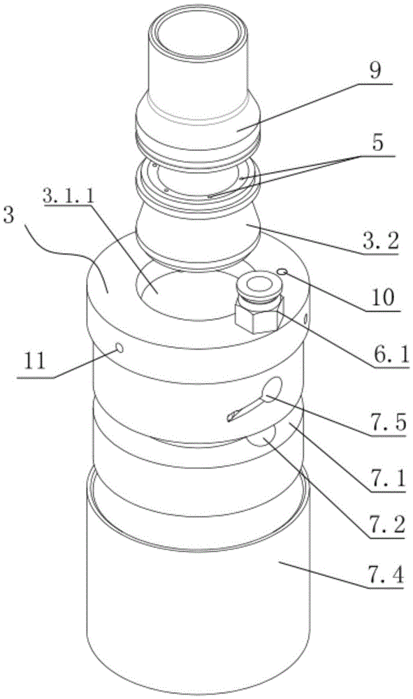
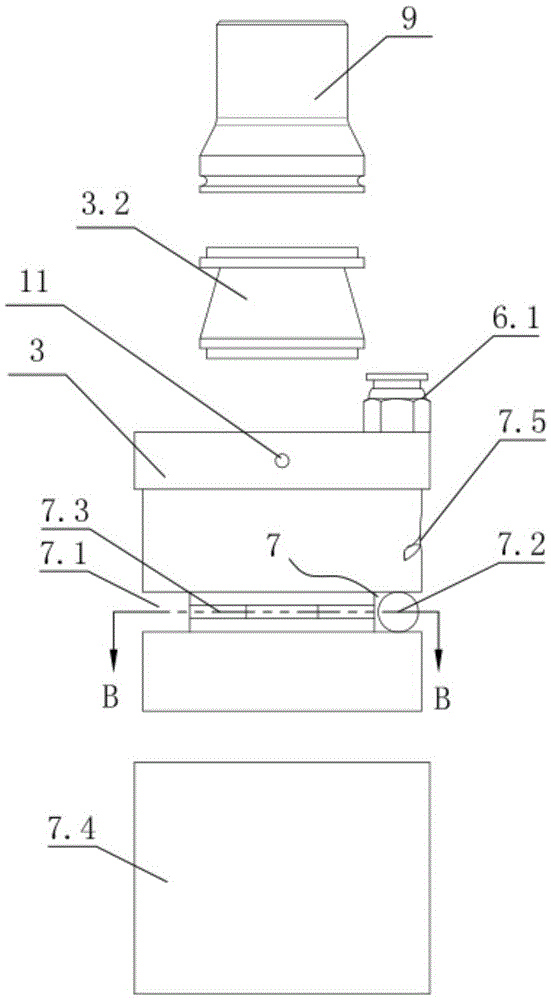
[0024] Such as figure 1 As shown, the present invention provides an automatic feeding device for an injection molding machine, which includes a feeding pipe 1 , one end of the feeding pipe 1 communicates with the injection molding machine, and the other end is placed in a storage barrel 2 . The communication with the injection molding machine referred to above can be directly connected with the mold cavity of the injection molding machine, and can also be connected with a container for temporarily storing plastic particles 4 such as a discharge barrel or a funnel on the injection molding machine. As the invention attached Figure 7 As shown, one end of the feeding pipe 1 communicates with the injection molding machine feeding cylinder 13, and the lower end of the injection molding machine feeding cylinder 13 shown communicates with the injecti...


PUM


Abstract

The present invention discloses an automatic material feeding apparatus of an injection molding machine. The automatic material feeding apparatus comprises a material feeding pipe (1), wherein one end of the material feeding pipe (1) is communicated with the injection molding machine, and the other end is placed in a material storage barrel (2). The automatic material feeding apparatus is characterized in that the material feeding pipe (1) is provided with a material feeding suction head (3), a material inlet channel (3.1) is arranged inside the material feeding suction head (3), the inner wall of the material inlet channel (3.1) is provided with at least a gas nozzle (5) for pushing plastic particles (4) to move ahead toward the material out end (3.1.1) direction along the material inlet channel (3.1), the gas nozzle (5) is communicated with the external gas source through a gas pipe (6), the gas pipe (6) is provided with a gas valve, and the gas valve is electrically connected with a control system (15). The present invention provides the automatic material feeding apparatus for the injection molding machine, wherein the automatic material feeding apparatus has characteristics of simple structure, low cost, stable performance, capability of long term continuous production, and resistance of overload damage caused by pipeline clogging.

Description

technical field [0001] The invention relates to the technical field of injection molding machines, in particular to an automatic feeding device for injection molding machines. Background technique [0002] With the rapid development of injection molding machine technology, its feeding method has gradually changed from manual feeding to automatic feeding, so as to achieve high efficiency and high precision in the injection molding process. However, most of the existing automatic feeding devices for injection molding machines adopt the method of vacuuming and sucking materials, such as the patent application with the patent application number 201210095330.4. Negative pressure is generated, so that the plastic particles in the storage box are sucked into the feeding barrel on the injection molding machine through the suction pipe for injection molding. And this type of existing automatic material suction machine often has the following disadvantages: 1) in the situation of con...

Claims


Application Information

Patent Timeline
Patent Type & Authority Patents(China)
IPC IPC(8): B29C45/18B65G53/24
CPCB29C45/18B65G53/24
Inventor 尤清森
Owner 宁波禾采医疗器械有限公司
Learn More