
Lighting device

A technology for lighting equipment and semiconductors, applied in lighting and heating equipment, lighting devices, components of lighting devices, etc., to achieve the effect of heat transfer

Inactive Publication Date: 2014-07-09
OSRAM GMBH
View PDF6 Cites 10 Cited by
  • Summary
  • Abstract
  • Description
  • Claims
  • Application Information

AI Technical Summary

Problems solved by technology

[0006] Furthermore, typical ballasts for LED-based light sources are mostly implemented as potential-free compact switching power supplies, which can typically have significant power losses of up to 20%

Method used


Image

  • Lighting device
  • Lighting device
  • Lighting device

Examples


Embodiment Construction

[0061] In the exemplary embodiments and figures, identical, identical or identically acting elements can always be provided with the same reference symbols. The shown elements and their mutual size relations are not to be regarded as true to scale, rather, individual elements, such as layers, may be shown exaggerated for better visibility and / or for better understanding. , components, devices and areas.

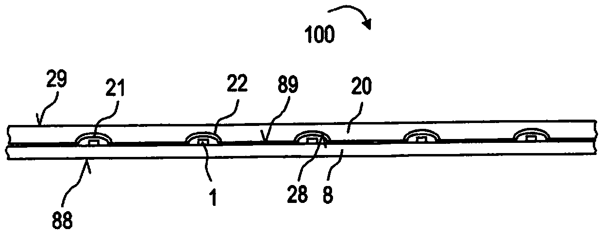
[0062] exist figure 1 A part of the lighting device 100 according to the first embodiment is shown in . The lighting device 100 has a plurality of light-emitting semiconductor chips 1 which are arranged on a carrier plate 8 . In the exemplary embodiment shown, the carrier plate has a plastic plate or a plastic layer on which a metallic conductive layer is arranged as a reflective mounting surface 89 , apart from the reflective semiconductor chips that emit light. The primary light emitted by 1 can also be used for the electrical connection of the semiconductor chip 1 .

...


PUM


Abstract

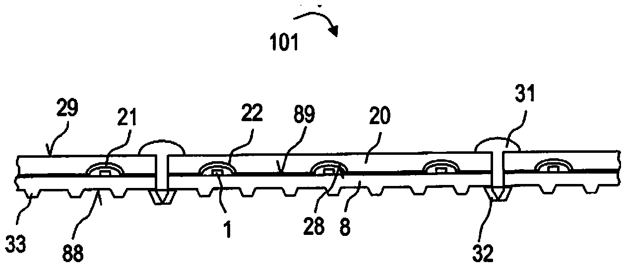
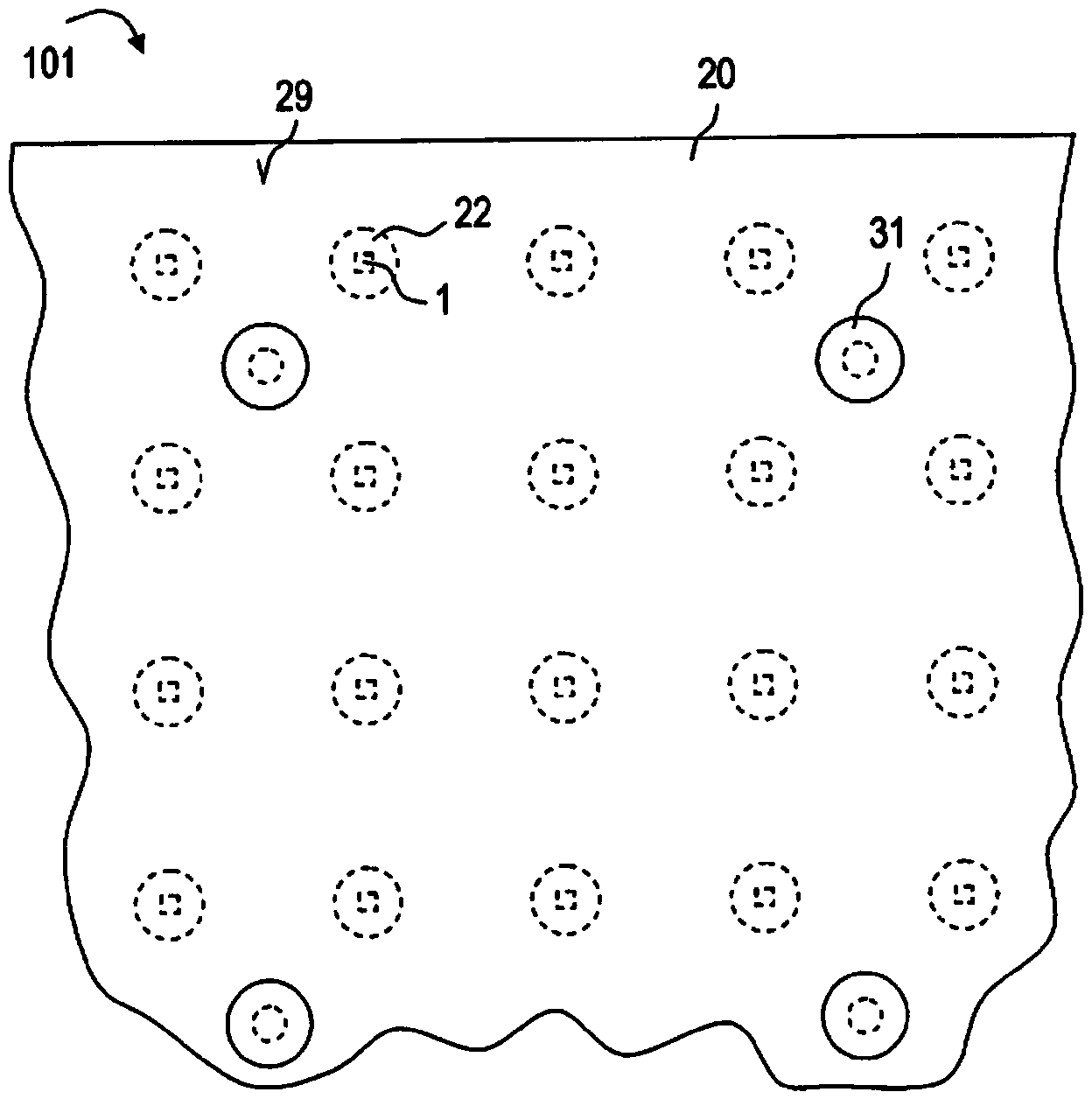
The invention relates to a lighting device for room lighting which has a carrier plate (8) having a reflective assembly surface (89) on which a plurality of light emitting semiconductor chips (1) spaced apart from each other is arranged, and furthermore a translucent or transparent emission plate (20) arranged downstream of the light emitting semiconductor chips (1) in the emission direction and having a light decoupling surface (29) facing away from the light emitting semiconductor chips (1), wherein the emission plate (20) has a plurality of recesses (22) which are each arranged after at least one semiconductor chip (1), and wherein each of the recesses (22) has a diffusor material and / or a wavelength conversion material (21) on the inner surface (28) facing the semiconductor chips (1), and spaced apart from the light emitting semiconductor chips (1).

Description

technical field [0001] A lighting device is proposed, eg for lighting a space. [0002] related application [0003] This patent application claims priority from German patent application 10 2011 112 710.4, the disclosure content of which is incorporated herein by reference. Background technique [0004] High light intensities are required for room lighting, so that high waste heat can also be generated when light-emitting diodes (LEDs) are used as light sources. Known LED-based light sources are therefore generally constructed taking into account, inter alia, the chip material and cooling material and usually have an active cooling device that cools the heat sink by means of a fan air flow. [0005] In order to generate mixed-color and in particular white light, LED-based light sources usually have light-emitting diode chips which are individually provided with phosphors. In order to be able to create a uniform color impression in the case of a light source with several ...

Claims


Application Information

Patent Timeline
Patent Type & Authority Applications(China)
IPC IPC(8): F21K99/00F21V9/40
CPCF21V3/04F21Y2105/12F21Y2105/10F21K9/60F21K9/64F21Y2115/10F21V13/14F21V9/32
Inventor 雷蒙德·奥伯施密德马丁·默克
Owner OSRAM GMBH
Learn More