Continuous composite plating sand overlying tank for diamond cutting line

A diamond cutting wire and diamond micropowder technology, applied in electrolytic coatings, coatings, electrolytic processes, etc., can solve the problems of long coating quality controllability and low electroplating efficiency, and achieve high coating quality controllability and high electroplating efficiency. , good heat resistance and wear resistance

Active Publication Date: 2014-07-02
JIANGSU XINGDA STEEL TYPE CORD
View PDF4 Cites 7 Cited by
  • Summary
  • Abstract
  • Description
  • Claims
  • Application Information

AI Technical Summary

Problems solved by technology

[0005] The present invention aims at the disadvantages of low electroplating efficiency, long length of the required plating tank and poor controllability of the coating quality in the existing diamond cutting wire composite electroplating process, and provides a simple structure, high electroplating efficiency, required plating tank length and poor controllability of the coating quality. The quality of the coating is highly controllable, and the diamond on the cutting line is evenly distributed, and the diamond cutting line with good bonding force between the coating and the diamond is continuously coated with a sand tank

Method used


Image

  • Continuous composite plating sand overlying tank for diamond cutting line
  • Continuous composite plating sand overlying tank for diamond cutting line

Examples


Embodiment 1

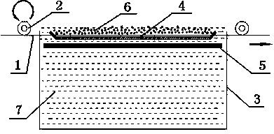
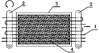
[0021] Embodiment one: see figure 1 with figure 2 As shown, a diamond cutting line continuous composite plating sand tank, including electroplating tank body 3, cathode roller 2, anode frame 5, sand tank 4 and wire wheel, the anode frame 5 is a tin-lead alloy mesh plate frame, the described sand-loading tank 4 is a reticulated flat tank, and baffles are arranged around the described reticulated flat tank, and the baffles at both ends of the reticulated flat tank are set in an inclined trapezoid and are attached with cotton balls, sponges or wool The brush material lightly rubs the steel wire, the nylon mesh with fine aperture is bonded on the described sand tank 4, the cathode roller 2 is connected with the negative pole of the power supply, the anode frame 5 is connected with the positive pole of the power supply, and the cathode roller 2 is connected with the positive pole of the power supply. Located on the outside of the electroplating tank body 3, the electroplating tan...

Embodiment 2

[0022] Embodiment two: with embodiment one, difference is: select the steel wire that diameter is 0.18mm for use, select the diamond micropowder that average particle diameter is 30 μ m for use, cut steel wire 1 winding electroplating tank body 3 two ends cathode roller 2 five circles, cathode roller 2 top The cutting steel wire 1 exposes the diamond micropowder 6 and is immersed in the plating solution 7, finally obtaining a diamond cutting wire with a diameter of 0.25mm.


PUM


Abstract

The invention discloses a continuous composite plating sand overlying tank for a diamond cutting line. The continuous composite plating sand overlying tank comprises an electroplating bath body, a cathode roller, an anode rack, a sand loading tank and a wire guiding wheel, wherein the cathode roller is connected with the cathode of a power supply, and the anode rack is connected with the anode of the power supply; the cathode roller is arranged on the outer side of the electroplating bath body; a plating solution is filled in the electroplating bath body; diamond micro-powder is loaded by the sand loading tank; the anode rack, the sand loading tank and a cutting steel wire wound at the upper part and lower part of the cathode roller are submerged in the plating solution; the anode rack is fixed below the sand loading tank; the cutting steel wire below the cathode roller is buried in the diamond micro-powder. The composite plating sand overlying tank has the characteristics of high electroplating efficiency, high controllability on the length of the needed electroplating bath body and the plating quality, strong binding force of cutting line diamond with a base body, good heat-resisting and abrasion-resisting properties and high cutting efficiency.

Description

technical field [0001] The invention relates to the technical field of electroplating equipment, in particular to a continuous composite sand plating tank for a diamond cutting line. Background technique [0002] With the rapid development of the semiconductor, integrated circuit and photovoltaic industries, the application of hard and brittle crystal materials such as crystalline silicon, sapphire, and quartz is becoming more and more extensive, which puts forward higher requirements for cutting and processing technology, especially for crystalline silicon, the next generation of integrated circuits will The use of large diameter and thin silicon wafers brings new challenges to the cutting technology. At present, the relatively mature cutting technology is the free abrasive wire saw cutting technology, that is, the mortar with abrasive is supplied to the saw wire at the same time of cutting, but the saw kerf loss is large, and it is difficult for the abrasive to enter the...

Claims


Application Information

Patent Timeline
IPC IPC(8): C25D17/00C25D15/00C25D7/06
Inventor 倪自飞王红志姚利丽刘祥
Owner JIANGSU XINGDA STEEL TYPE CORD
Why Eureka
Try Eureka