
RFID (Radio Frequency Identification) tag and manufacturing method thereof

A technology of RFID tags and manufacturing methods, applied in the field of radio frequency identification, can solve the problems of being unable to be used as livestock ear tags, complex manufacturing process, high cost, etc., and achieve the effects of easy mass production, improved gain performance, and light weight

Active Publication Date: 2014-06-25
SHANGHAI ADVANCED RES INST CHINESE ACADEMY OF SCI
View PDF3 Cites 0 Cited by
  • Summary
  • Abstract
  • Description
  • Claims
  • Application Information

AI Technical Summary

Problems solved by technology

[0006] The RFID tag with the above structure has a planar structure and is relatively long, so it cannot be used as an ear tag for livestock (pigs, cattle, sheep), and the manufacturing process is complicated and the cost is high

Method used


Image

  • RFID (Radio Frequency Identification) tag and manufacturing method thereof
  • RFID (Radio Frequency Identification) tag and manufacturing method thereof
  • RFID (Radio Frequency Identification) tag and manufacturing method thereof

Examples


Embodiment 1

[0052] RFID tags, including tag parts and casings;

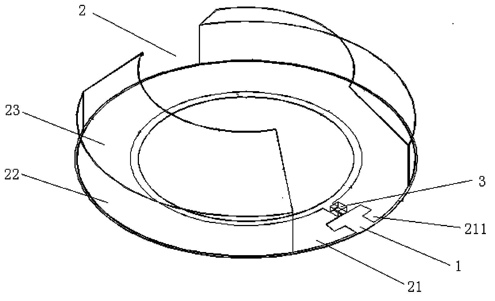
[0053] The label section, such as figure 2 As shown, it includes an insulating film 1, a tag antenna 2, and a tag chip 3;

[0054] The tag antenna 2 is attached to the upper surface of the insulating film 1;

[0055] The tag antenna 2 includes an annular metal patch 21, a first cylindrical metal patch 22, a second cylindrical metal patch 22, a first frustum-shaped metal patch 23, a second frustum-shaped metal patch Metal patch 23;

[0056]The annular metal patch 21 has a gap;

[0057] Two short leads 211 are respectively formed on the left and right sides of the notch of the annular metal patch 21;

[0058] The bottom edge of the first cylindrical metal patch 22 is connected to the outer edge of the annular metal patch 21 on the left side of the notch;

[0059] The bottom edge of the second cylindrical metal patch 22 is connected with the outer edge of the annular metal patch 21 on the right side of the gap;

[0060] ...

Embodiment 2

[0066] Based on embodiment one,

[0067] The RFID tag is an ultra-high frequency (UHF) RFID tag; the tag antenna 2 is a dipole antenna;

[0068] The label chip is welded together with two short leads on the inner edge of the annular metal patch 21 in an upside-down manner;

[0069] The insulating film 1 is a PET (polyethylene terephthalate) film or a PI (polyimide) film;

[0070] The metal patch (annular metal patch 21, the first cylindrical metal patch 22, the second cylindrical metal patch 22, the first frustum-shaped metal patch 23, the second frustum-shaped metal patch The patch 23) is an aluminum patch or a copper patch.

[0071] Preferably, the insulating film 1 has a thickness of 10-200 μm, and the metal patch has a thickness of 0.01-0.1 mm.

Embodiment 3

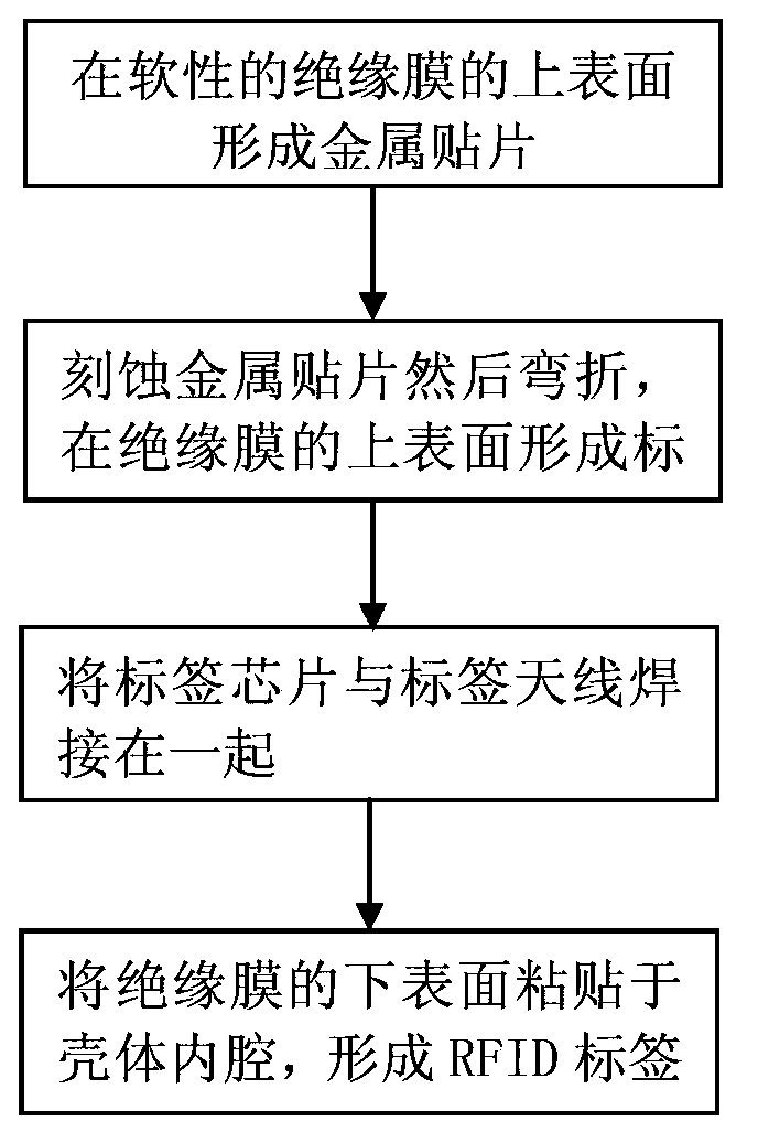
[0073] Manufacturing methods of RFID tags, such as image 3 shown, including the following steps:

[0074] one. Form a metal patch on the upper surface of the flexible insulating film;

[0075] Preferably, the insulating film is PET (polyethylene terephthalate) or PI (polyimide) film, with a thickness of 10-200 μm;

[0076] Preferably, the metal patch is an aluminum patch or a copper patch, with a thickness of 0.01-0.1mm;

[0077] two. Etching the metal patch and then bending it to form a tag antenna on the upper surface of the insulating film 1;

[0078] three. Welding the tag chip and the tag antenna together to form a processed soft tag part;

[0079] Four. Paste the lower surface of the insulating film (attached with tag antenna and tag chip) to the inner cavity of the housing to form an RFID tag.


PUM

PropertyMeasurementUnit
Thicknessaaaaaaaaaa
Thicknessaaaaaaaaaa

Abstract

The invention discloses a RFID (Radio Frequency Identification) tag. The RFID tag comprises a tag part and a shell; the tag part comprises an insulated film, a tag antenna, and a tag chip; the tag antenna is attached to the upper surface of the insulated film; the tag antenna comprises a circular metal patch, a first cylindrical surface-shaped metal patch, a second cylindrical surface-shaped metal patch, a first conical surface-shaped metal patch and a second conical surface-shaped metal patch; the circular metal patch is provided with a notch; the left side and the right side of the notch of the circular metal patch respectively form two short leads; the tag chip is welded with the two short leads of the inner edge of the circular metal patch; the shell is made of hard insulating material, and the shape of the inner cavity is matched with the shape of the tag antenna; and the lower surface of the insulated film of the tag part is attached to the inner cavity of the shell. The invention also discloses a manufacturing method of the RFID tag. The RFID tag is small in size and simple in manufacturing technology, and is suitable for being mounted on a livestock ear.

Description

technical field [0001] The present invention relates to radio frequency identification technology (Radio Frequency Identification, abbreviated as RFID), in particular to an RFID tag and a manufacturing method thereof. Background technique [0002] Radio Frequency Identification (RFID) is a technology that uses radio frequency signals to achieve non-contact information transmission through spatial coupling (alternating magnetic field or electromagnetic field) and achieve identification purposes through the transmitted information. Compared with traditional identification technologies (two-dimensional codes, barcodes, etc.), RFID technology has the characteristics of unique marking, large information capacity, fast and convenient reading, multi-label reading, and data encryption. After years of development, it has been widely used in item tracking, aviation luggage sorting, factory assembly lines, car anti-theft, electronic tickets, animal management, commodity anti-counterfei...

Claims


Application Information

Patent Timeline
IPC IPC(8): G06K19/077
Inventor 张志勇张钊锋
Owner SHANGHAI ADVANCED RES INST CHINESE ACADEMY OF SCI
Learn More